KPM KB2 is a non-contact paper breakage detector launched by ABB, with hundreds of installation cases worldwide, recognized as an excellent paper breakage detection device in the market. It can be installed above or below the paper web, suitable for environments with high dust, steam, high temperature, and limited space. It keeps the sensor head clean through air blowing and can reliably monitor paper breakage in harsh environments.
Core functions and features
Flexible detection light source: equipped with RGB or infrared light sources, it can perform well in various paper and cardboard products and applications regardless of the color of the paper and cardboard. RGB color measurement can handle all paper, mesh, and woolen colors, ensuring reliable fracture detection. In addition to open traction applications, it can also detect fractures in woolen, mesh, and even drum backgrounds.
Fast fracture detection: Using digital signal processing technology, thousands of measurements are taken of all signals per second, and the backlight intensity is measured to resist the influence of environmental light changes. The minimum delay for fracture detection is only 15ms, and users can select the number of measurement cycles for fracture alarm through digital filtering.
Convenient setup and operation: Equipped with a large display screen and a logical user interface, the fracture detection setup can be easily completed by selecting the measurement value with the largest signal difference. The fracture and maintenance alarm can be connected to PLC or DCS, and color measurement PC software can also be selected for monitoring, including data collection function.
Adapt to harsh environments: It can maintain high reliability even in high humidity environments. When the sensor head is exposed to high temperatures, the electronic unit can be installed outside the machine cover through fiber optic cables.
Specification parameters
Environmental temperature sensor head and fiber optic cable: -10-180 º C (15-356 º F); Electronic unit: -10-60 º C (15-140 º F)
Fiber optic cable conduit requires a flexible airtight conduit with an inner diameter of at least 19mm (3/4 “), which can be optionally selected
19mm (three-quarters “) BSP conduit connection
Install the sensor 5-30cm (2-12 “) away from the paper web
LED pulse frequency 1kHz
Power supply 90-264VAC, 50/60Hz or 24VDC
Power consumption 15W
Shell protection level IP 66 (Nema 4x)
Blow air connection dry instrument air, 6-4mm (¼ “) connector, normal consumption 80l/min (21gpm)
Digital output with 2 normally open or normally closed contacts, maximum 250VAC, 2A; 220VDC、2A, Used for breaking signals and maintenance alarms
Alarm output delay: minimum 15ms after actual fracture
Analog output (optional) 3 4-20mA, maximum 600 Ω (ohms), isolated
Dimensions (length x height x width) and weight: Electronic unit: 323 x 237 x 70mm (12.7 x 9.3 x 2.8 “), 3kg (6.6lbs); Sensor head: diameter 33mm (1 1/4 “), stainless steel 316, tube length 1500mm (59”), 4kg (9lbs)
Application scenarios
Mainly used in the pulp and paper industry, it is used to monitor the breakage of paper sheets during the production process of paper and cardboard. It can be installed in different positions of the paper machine, such as the mesh section, press section, drying section, etc., to detect paper sheet breakage in a timely manner and issue alarm signals, so that operators can quickly take measures to reduce production losses caused by paper sheet breakage, improve production efficiency and product quality.
Brand background
This product is produced by ABB, a leading global electrical and automation enterprise with operations in multiple countries and regions around the world. ABB has deep technological accumulation and extensive influence in the fields of power, industry, transportation, and infrastructure. It has always been committed to technological innovation and provides advanced solutions for various industries. KPM KB2 paper breakage detector is one of ABB’s important products in the automation solutions of pulp and paper industry, reflecting ABB’s technical strength in this field and deep understanding of industry needs.
AO845A is an analog output module specially designed by ABB for industrial automation scenarios, belonging to the S800 I/O family. This module is mainly used to convert the digital signals inside the controller into analog signals, in order to drive actuators or other analog devices. It plays a key role in industrial automation and control systems, and can achieve precise control of various industrial processes. It supports single redundancy or redundant applications and has 8 unipolar analog output channels, which can meet the diverse control needs of complex industrial systems. At the same time, the module has a periodic self diagnostic function, which can monitor the real-time operation status of the module and ensure the stable and reliable operation of the system.
Brand background
ABB, as a globally renowned technology leader in the field of electrical and automation, has a long history of over 140 years. The company operates globally and has over 105000 employees. ABB has always focused on technological innovation, deeply integrating engineering experience with digital technology to provide advanced solutions for various industries, helping customers achieve efficient operations, improve energy efficiency and production efficiency, and promote sustainable development in various industries. In the field of industrial automation, ABB relies on its profound technical accumulation and rich project experience, and its products are widely used in various industries, trusted by global customers.
Basic information
Product model: TP854 (or TP854A, TP854B)
Product Code: 3BSE025349R1
Product Description: A base plate designed specifically for CI854, CI854A, and CI854B, belonging to the Modular Termination-Unit.
Package: Yes CI854K01(3BSE025961R1)、CI854AK01(3BSE030220R1)、CI854BK01(3BSE069449R1) The components of the kit.
Size and weight
Product net depth/length: 216mm
Product net height: 49.5mm
Product net width: 72mm
Net weight of product: 0.234kg
Core functions
Analog signal output: It can output 4… 20 mA standard analog signals, which are used to drive devices that require continuous adjustment such as regulating valves, frequency converters, and motor controllers, achieving precise control of industrial processes.
HART communication: Supports HART pass through communication function, facilitating device status monitoring and remote parameter configuration, and improving system management efficiency. Only point-to-point communication is supported, and the channel used for HART communication requires an output filter to be enabled.
Self diagnostic function: Periodically perform self diagnosis, monitor and report multiple faults in real time. External channel errors, such as low output circuit supply voltage, output current less than the set value, and set value greater than 1 mA (open circuit), will be reported (only reported on active channels); Internal channel error, reported when the output circuit cannot provide the correct current value, the redundant centering module will be instructed by the module bus master device to enter an error state; Module errors, including output transistor errors, short circuits, checksum errors, internal power supply errors, status link errors, watchdog or erroneous OSP behavior, will be reported.
Working principle
The control system sends digital signals to the AO845A module, and the digital to analog converter (DAC) inside the module converts the received digital signals into analog signals. Afterwards, the analog signal is output to the external control device through the analog output channel. For example, in a temperature control system, the PLC calculates a control signal based on the difference between the current temperature value and the set temperature, and sends it in digital form to the AO845A module. The AO845A module converts it into a corresponding 4-20 mA analog current signal output to control the working power of the heater and adjust the temperature.
Key advantages
High reliability: Equipped with comprehensive self diagnostic functions and short-circuit protection mechanisms, it can promptly detect and handle faults, ensuring stable operation in complex industrial environments. Through various international certifications such as CE, UL, etc., it meets strict electrical safety standards and can adapt to the safety requirements of different regions and industries.
Flexible compatibility: Supports single redundancy or redundant applications, can be used in conjunction with multiple MTU (module terminal units), suitable for industrial automation systems of different architectures, and has strong universality and compatibility.
Convenient communication: With the help of HART communication technology, seamless integration with various devices can be achieved, facilitating real-time data exchange and device diagnosis, facilitating remote management and maintenance, reducing manual intervention, and improving overall system operation and maintenance efficiency.
Precise control: With a resolution of 12 bits and a maximum error as low as 0.1%, it can accurately output analog signals, meeting the extremely high requirements for control accuracy in industrial application scenarios.
Precautions
Installation aspect: During installation, relevant electrical specifications and operation guidelines should be followed to ensure the correct installation of modules and correct circuit connections, in order to prevent malfunctions caused by improper installation. The module size is compact, and the installation space should be reasonably planned to ensure good heat dissipation.
Signal configuration: It is necessary to correctly configure the signal mode (such as active or passive mode) according to the actual application scenario. For equipment operating in different explosion-proof areas, corresponding configuration rules should be followed.
Wiring requirements: Use shielded cables for process connections, especially when using HART communication, to reduce electromagnetic interference and ensure the stability and accuracy of signal transmission.
Address setting: For devices with PROFIBUS PA, the bus address should be checked or configured before startup to ensure that the address is within the valid range (0… 125) and unique within the network segment.
Maintenance: Regularly check the working status of the module, observe the front LED indicator lights, and promptly troubleshoot and handle any abnormalities. When the system malfunctions, targeted maintenance can be carried out based on the diagnostic information of the module.
AO845A is an analog output module suitable for System 800xA systems, supporting single redundancy or redundant applications, equipped with 8 unipolar analog output channels. The module has a periodic self diagnostic function, which can monitor various fault states such as external channel errors, internal channel errors, and module errors, ensuring operational reliability.
Core functions and features
Output capability: 8 channels of 4-20 mA, meeting the analog signal output requirements of industrial sites.
Redundancy support: can be used in redundant application scenarios to enhance system stability.
Isolation protection: 8 channels are isolated from ground as a group, and the analog output has short-circuit protection function (for ZP or+24 V).
Communication function: Supports HART pass through communication, facilitating device status monitoring and parameter configuration.
Self diagnosis: Periodically self diagnose and promptly report various faults, including external channel errors (such as low supply voltage, open circuit, etc.), internal channel errors (such as abnormal output circuit), and module errors (such as output transistor faults, short circuits, checksum errors, etc.).
Specification parameters
Basic parameter model: AO845A; Product Code: 3BSE045584R1; Type: Analog output; Signal specification: 4.20 mA; Number of channels: 8; Does it support HART: Yes; Does it support SOE: No; Redundancy: Support; High integrity: No; Intrinsic safety: No; Mechanical specification: S800
Performance parameter resolution: 12 bits; Isolation method: Group level and grounding isolation; Over/under range: ± 15%; Maximum output load: 750 Ω; Maximum error: 0.1%; Temperature drift: maximum 50 ppm/° C; rise time: 23 ms when output filter is disabled, maximum 4 mA/12.5 ms when enabled; Input filter (0-90% rise time): 23 ms (0-90%), maximum 4 mA/12.5 ms; Update cycle: 10 ms; Current limit: Short circuit protection current limiting output; Maximum on-site cable length: 600 meters (656 yards)
Electrical parameters: Rated insulation voltage: 50 V; Dielectric test voltage: 500 V AC; Power consumption: typical 3.5 W;+5 V Modulus current consumption: maximum 125 mA;+24 V external current consumption: 218 mA
Diagnosis and indication front-end LED: F (fault), R (operation), W (warning) O(SP); Monitoring status indication: module error, module warning, channel error
Environment and Certification CE Mark: Yes; Electrical safety: compliant with IEC 61131-2, UL 61010-1, UL 61010-2-201; Dangerous Place Certification: C1 Div2 cULus, C1 Zone2 cULus, ATEX Zone 2; Classification society certification: BV, DNV-GL, LR; Protection level: IP20 (according to IEC 60529); Corrosive environment grade: ISA-S71.04 G3; Working climate conditions: 0 to+55 ° C (storage -40 to+70 ° C), relative humidity 5-95%, no condensation (compliant with IEC/EN 61131-2); Pollution level: Level 2 (according to IEC 60664-1); Mechanical working conditions: comply with IEC/EN 61131-2; EMC: Complies with EN 61000-6-4 and EN 61000-6-2; Overvoltage category: compliant with IEC/EN 60664-1 and EN 50178; Equipment category: Class I (according to IEC 61140, grounding protection); Maximum ambient temperature: 55 ° C (131 ° F), 40 ° C (104 ° F) for compact MTU vertical installation; Compliant with RoHS (Directive 2011/65/EU) and WEEE (Directive 2012/19/EU)
Compatible with MTU: TU810, TU812, TU814, TU830, TU833, TU842, TU843, TU852; Key control code: DB
Size and weight width: 45 mm (1.77 inches); Depth: 102 mm (4.01 inches), including connector 111 mm (4.37 inches); Height: 119 mm (4.7 inches); Weight: 0.21 kg (0.46 pounds)
Related products
Including TU810V1, TU812V1, TU814V1, TU830V1, TU833, TU842, TU843, TU852, etc.
Key advantages
High reliability: Equipped with comprehensive self diagnostic functions and short-circuit protection, it can promptly detect and report faults, ensuring stable system operation.
Flexible compatibility: Can be used in conjunction with multiple MTUs, suitable for single redundant or redundant application scenarios, and adaptable to different system architecture requirements.
Convenient communication: Supports HART protocol, facilitating remote monitoring and configuration, and improving system management efficiency.
Strong environmental adaptability: capable of working in a wide range of temperature, humidity, and corrosive environments, compliant with multiple international standards and certifications, suitable for complex industrial environments.
FS450R12KE3+AGDR-71C is an integrated circuit product launched by ABB, which belongs to the IGBT related module combination. At present, there are 500 pieces of brand new original inventory, which can provide key circuit control functions for various electronic devices and industrial control systems. It plays an important role in the field of electronic component applications and can meet the circuit control needs in different scenarios.
Brand background
This product is manufactured by ABB company. ABB is a globally renowned electrical and automation enterprise with a history of over 130 years. Its business covers multiple countries and regions around the world, and it has deep technological accumulation and extensive influence in fields such as power, industry, transportation, and infrastructure. ABB has always been committed to technological innovation. Its products are known for their high quality, high reliability and progressiveness. They occupy an important position in the global market and provide advanced solutions and product support for many industries.
Specification parameters
Due to the lack of detailed specifications for the product in the existing information, combined with the relevant categories of IGBT modules and common industry standards, it is speculated that the product may have the following similar specifications (specific to the product datasheet):
Voltage level: may be suitable for medium to high voltage scenarios, such as 1200V commonly seen in related product series.
Current capacity: As a power device, it may have a high current carrying capacity to meet the power requirements of industrial equipment.
Packaging form: Adopting packaging suitable for industrial applications, with good heat dissipation performance and mechanical strength to adapt to complex industrial environments.
Core functions
As an integrated circuit product, its core functions may include achieving efficient switch control of the circuit. In scenarios such as power conversion and motor drive, it can quickly switch circuit states, control current on/off, and effectively manage and distribute power. At the same time, it may have certain protection functions, such as overcurrent protection, overvoltage protection, etc., to ensure the safe operation of circuits and related equipment.
Working principle
It is speculated that its working principle is based on the working characteristics of IGBT (Insulated Gate Bipolar Transistor), which controls the gate voltage to achieve the on and off of the transistor. When a forward voltage is applied to the gate, the device conducts and current can pass through; When the gate voltage is removed or a reverse voltage is applied, the device is turned off and the current is cut off. AGDR-71C may serve as a driving module to provide suitable driving signals for FS450R12KE3, ensuring its stable and reliable operation and achieving precise control of the circuit.
Key advantages
Reliable Quality: Made by ABB, following strict quality control standards, ensuring 100% functional integrity and maintaining stable performance over long periods of use.
Stable supply: Currently, there are 500 pieces in stock, and delivery can be made within 2-3 days after payment, which can quickly respond to customer needs and reduce project delays caused by stock shortages.
Widely applicable: As a universal integrated circuit product, it can be applied to various electronic devices and industrial control systems, with strong universality and compatibility.
Precautions
Installation and use: During installation, it is necessary to follow relevant electrical specifications and operating instructions to ensure correct connection of circuits and avoid product damage or circuit failure caused by improper installation.
Storage conditions: It should be stored in a dry, ventilated, and non corrosive gas environment, avoiding direct sunlight and high temperature environments to prevent product performance from being affected.
Static electricity protection: Effective static electricity protection measures should be taken during the handling process, such as wearing anti-static wristbands, to prevent static electricity from damaging the product.
Application scenarios
FS450R12KE3+AGDR-71C can be widely used in the field of industrial automation, such as motor drive systems, power converters, uninterruptible power supplies (UPS) and other equipment, to achieve power conversion, control and distribution. In the field of new energy, inverters such as wind and photovoltaic power generation may also play an important role in ensuring efficient and stable energy conversion processes. In addition, there is potential application value in electronic devices related to rail transit, household appliances, and other fields.
PNI800 is a Plant Network Interface device launched by ABB, belonging to ABB Ability ™ Symphony ® Plus hardware series. It is mainly used to achieve real-time bidirectional communication between SD series controllers and PC workstations running S+Engineering, HMI (such as SPO or 800xA Operations) or general interface software (such as Harmony OPC Server). It is also an important component of PN800 real-time control network, supporting data exchange with PC workstations running SPE (Engineering), HMI or SCADA software applications.
Core functions and features
Real time communication: As a real-time data server, it supports bidirectional real-time communication between SD series controllers and various software applications, with a transmission speed of up to 100 MBps.
Redundancy support: PN800 factory network redundancy is implemented based on the Parallel Redundancy Protocol (PRP) of IEC 62439, consisting of two topologically identical local area networks (PN800A and PN800B), eliminating single point of failure and achieving zero switching time in case of network component failure; As a dual connection node (DANP), it connects to two local area networks and provides line redundancy.
Connectivity: Supports up to 10 SPE client connections and can handle up to 30000 HMI tags; Communication connection is achieved through two Ethernet RJ45 connectors on the MB805 base, and there is one mini USB diagnostic port at the front end of the module.
Flexibility and maintainability: Supports hot swapping, making it easy to replace and maintain online; The functionality can be virtualized as “VPNI” optional software, suitable for various software applications, but performance and capacity may differ from PNI800.
Specification parameters
Basic Information Product Number: PNI800K01; Lifecycle status: Active; Protocol: Harmony API (based on Ethernet TCP); Module redundancy: none; Exterior specifications: xA Style (186mm); Installation method: Horizontal arrangement
Power Requirements Module Power Requirements: 200 mA @ 24 VDC ± 10%; Power connection: TB1 on MB805 base; Overvoltage category: Power supply is Class 1 (tested according to IEC/EN 61010-1)
Environmental parameters: Operating temperature: 0 to+55 ° C; Storage temperature: -40 to+85 ° C; Relative humidity: 20% to 95% at 40 ° C (no condensation, tested according to relevant standards); Protection level: IP20 (according to EN 60529, IEC 529)
Reliability index MTBF (based on MIL-HDBK-217-FN2): PNI800 PR is 135873 hours, MB805 PR is 2583516 hours; MTTR: PNI800 is 1 hour, MB805 is 8 hours
Compliance with multiple electromagnetic compatibility standards (such as ESD, surge, electrical fast transient, etc. immunity testing, radiation and conducted emission testing); CSA certification: applicable to ordinary (non hazardous) locations, as well as Class 1, Zone 2, Groups A, B, C, and D hazardous non flammable locations; Equipped with CE mark, compliant with EMC directive and low voltage directive; Compliant with RoHS Directive (2015/863) and WEEE Directive (Directive/2012/19/EU), etc
Key advantages
High reliability: With the help of PRP redundancy protocol and dual connection design, the reliability of the control network is greatly improved, reducing the risk of system interruption caused by network failures.
Efficient communication: With a transmission speed of 100 MBps and powerful connectivity, it can meet the needs of large-scale real-time data transmission and ensure rapid system response.
Good compatibility: Supports multiple software applications and communication protocols, seamlessly integrates with ABB’s multiple systems and software (such as 800xA, Symphony Plus, etc.).
Strong environmental adaptability: Through multiple environmental and electromagnetic compatibility tests, it can work stably in a wide range of temperature, humidity, and complex electromagnetic environments.
Precautions
During installation, it is necessary to follow the prescribed installation details (MB805, 1=E, 2=C) to ensure a stable installation.
Although hot plugging is supported, the correct operating procedures must still be followed during the replacement process to avoid equipment damage or communication interruption caused by improper operation.
The use of equipment must comply with the requirements of its certified location and cannot be used in hazardous areas or environmental conditions beyond the prescribed limits.
When virtualizing as “VPNI” software, it is important to pay attention to the performance and capacity differences between it and PNI800, and choose the appropriate application form based on actual needs.
Application scenarios
It is mainly used in the field of industrial automation, especially in scenarios that require high reliability real-time control networks, such as large-scale industrial control systems in the power, chemical, metallurgical and other industries. As a key interface connecting the controller with various engineering and monitoring software, it ensures the efficient and stable operation of the entire system. For example, in the control system of a power plant, real-time data exchange between SD series controllers, HMI operating interfaces, and engineering software is implemented to ensure real-time monitoring and parameter adjustment of the power generation process.
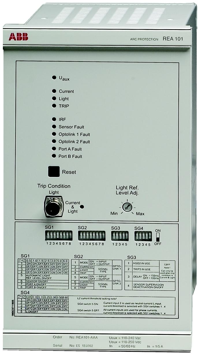
REA 101 is an arc protection relay (central unit) launched by ABB, which is the core component of REA 10_ arc protection system. It is mainly used in low-voltage or medium voltage air insulated metal enclosed switchgear, and can quickly send tripping commands to all circuit breakers that may supply power to arc faults, in order to minimize the damage caused by arc faults.
Brand background
REA 101 is produced by ABB company. ABB is a leading global enterprise in electrical and automation technology, with business covering multiple fields such as power, industry, transportation, and infrastructure. It has over 130 years of technological accumulation and innovative experience. Its products are renowned for their high quality, performance, and reliability, and have a wide influence in the field of industrial automation control. REA 101 is a reflection of its technical strength in the field of arc protection.
Specification parameters
Current input rated current 1A/5A; Continuous load current 4A/20A; Instantaneous current of 100A/500A per second; Dynamic withstand current (half wave value) 250A/1250A; Input impedance<100m Ω/<20m Ω; rated frequency 50/60Hz
Output HSO1 and HSO2: rated voltage of 250V DC/AC, continuous carrying of 1.5A, on-off of 30A in 0.5 seconds, on-off of 15A in 3 seconds, DC breaking capacity (when L/R<40ms) of 5A/3A/1A at 48V/110V/220V, respectively
TRIP3: Rated voltage 250V DC/AC, continuous load capacity 5A, on-off 30A in 0.5 seconds, on-off 15A in 3 seconds, DC breaking capacity (when L/R<40ms) 5A/3A at 48V/110V/220V respectively
IRF signal contact: rated voltage 250V DC/AC, continuous load 5A, on-off 10A in 0.5 seconds, on-off 8A in 3 seconds, DC breaking capacity (when L/R<40ms) 1A/0.25A/0.15A at 48V/110V/220V respectively
Control input (reset) rated voltage: 24/48/60/110/220/250V DC, 110/120/220/240V AC; Scope of work: 18-300V DC, 18-265V AC; Control current of 1.5-20mA; minimum pulse length of 1s
The optional action delay for circuit breaker failure protection is 100ms/150ms; The accuracy of HSO2 action time is ± 5% of the set value; TRIP3 is ± 5% of the set value+5-15ms
Rated voltage of power supply: 110/120/220/240V AC, 110/125/220/250V DC; REA101-CAA and REA101-CAAG are 24/48/60V DC
Voltage variation range: AC is 85-110% Ur, DC is 80-120% Ur
Power consumption is about 9W/12W in static/working state; The maximum output power of the port is about 19W; the maximum power consumption when connecting 10 expansion units is less than 50W
The maximum length of the sensor fiber is 60m when there is no connector or 1 connector; 50m when there are 2 connectors; 40m when there are 3 connectors; the working temperature range is -35-+80 ° C; the minimum bending radius is 50mm
The maximum total length of the connecting chain between the central unit and the expansion unit of the connecting cable is 40m
Optolink communication plastic fiber maximum length 40m; glass fiber maximum length 2000m
Set the current range with step sizes of 0.5, 1.0, 1.5, 2.5, 3.0, 5.0, and 6.0 times the rated current; Neutral line current setting step size 0.05, 0.10, 0.15, 0.25, 0.3, 0.5, 0.6 times rated current; Action accuracy is ± 5% of the set value or ± 2% of the rated current
Total action time HSO1 and HSO2<2.5ms; TRIP3<15ms
Environmental testing operating temperature range -10-+55 ° C; transportation and storage temperature range -40-+70 ° C; meets multiple environmental testing standards
The protection level of the shell is IP20; Weight approximately 4.6kg
Insulation test dielectric test 2kV, 50Hz, 1min; Impulse voltage test 5kV, 1.2/50 µ s, 0.5J; Insulation resistance>100M Ω (500V DC)
Electromagnetic compatibility meets multiple EMC testing standards, such as 1MHz pulse interference, electrostatic discharge, radio frequency electromagnetic field interference, etc
Core functions
Overcurrent detection: It can perform three-phase or two-phase neutral line overcurrent detection, with adjustable current threshold, and can quickly respond to fault currents.
Arc light detection: Detect arc light through fiber optic sensors or lens sensors, activate when the light signal exceeds the set reference level, and support automatic or manual backlight compensation.
Trip output: Equipped with two high-speed solid-state (IGBT) outputs (HSO1, HSO2) and one overload relay output (TRIP3), used for circuit breaker tripping. The tripping condition can be set to meet both the optical signal and overcurrent signal or only the optical signal.
Expansion unit connection: Connect expansion units (such as REA103, REA105, REA107) through ports A and B. Each port can cascade up to 5 expansion units to expand protection range and selectivity.
Optolink communication: Two Optolink communication links can transmit optical signals, overcurrent signals, trip signals, etc. between central units to achieve collaborative protection.
Circuit breaker failure protection: When the circuit breaker fails to successfully disconnect the fault current, a trip command is issued to the upstream circuit breaker after a set delay.
Self monitoring: Continuously monitor the sensor fiber optic circuit, operating voltage, wiring between the central unit and expansion unit, etc. When a fault occurs, activate the corresponding indicator light and reset the IRF relay.
Working principle
REA 101 monitors fault current through overcurrent detection unit, and detects the light signal generated by arc light through arc light detection unit. When both overcurrent signal and optical signal are received simultaneously (and there is no working voltage fault signal), the tripping output is triggered, causing the circuit breaker to operate and cut off the fault circuit. Through Optolink communication, information exchange between central units can be achieved, and combined with extension units, the protection range can be expanded and selective tripping can be achieved. The self-monitoring unit monitors the equipment status in real-time to ensure the reliable operation of the system.
Key advantages
Quick response: The total action time is short (HSO1 and HSO2<2.5ms, TRIP3<15ms), which can quickly cut off faults, reduce equipment damage and personnel injury risks.
High reliability: equipped with comprehensive self-monitoring function, timely detection and indication of faults; Adapt to complex industrial environments through multiple rigorous insulation and electromagnetic compatibility tests.
Strong flexibility: Supports multiple sensors (fiber optic sensors, lens sensors), can operate independently or work in conjunction with other central units and expansion units to adapt to different protection needs.
Easy to expand: By connecting expansion units through ports, the protection range can be flexibly expanded according to the system size, improving system selectivity.
Accurate protection: dual detection of overcurrent and arc light to avoid misoperation and ensure reliable operation in the event of actual arc light failure.
Precautions
Safe operation: comply with national and local electrical safety regulations, only qualified electricians are allowed to carry out electrical installations; The equipment framework needs to be reliably grounded; The sensor fiber should be handled carefully to avoid sharp bends (minimum bending radius 50mm), and should not be placed on the ground during installation to prevent stepping on it; When changing settings and configurations, the auxiliary power supply needs to be disconnected.
Installation settings: The sensor fiber end needs to be protected to avoid unnecessary triggering; When connecting expansion units, pay attention to the port switch settings, and the last expansion unit needs to be connected to a terminal resistor; Settings and configuration changes need to be made with the auxiliary power disconnected.
Maintenance testing: Regularly check the current measurement function, optical signal transmission, etc; Follow the prescribed steps when testing the arc protection system to ensure its normal operation.
Environmental requirements: Use within the specified range of temperature, humidity, and other environmental parameters to avoid extreme environmental conditions affecting equipment performance.
Similar model supplement
REA103: Expansion unit that can add an arc light sensor circuit to expand the protection area and assist REA101 in achieving more comprehensive arc light monitoring.
REA105: Expansion unit with trip output, capable of selective tripping. When the arc fault is located behind a specific circuit breaker, it accurately controls the corresponding circuit breaker action, enhancing system selectivity.
REA107: Expansion unit with 8 lens sensor inputs, suitable for arc light monitoring of specific compartments, improving monitoring specificity.
Application scenarios
Mainly used for arc protection of low or medium voltage air insulated metal enclosed switchgear, such as power distribution systems in substations and industrial plants. A circuit breaker compartment that can protect busbars, outgoing feeders, cable terminals, etc. By cooperating with expansion units, it achieves comprehensive, fast, and reliable arc fault protection for complex distribution systems, suitable for electrical safety protection in fields such as power and industry.
Product description: CEX Bus terminal, equipped with a 25 pin DB25P male connector, fixed with screws; It must be installed on the last unit of the CEX bus.
Product type: Prefabricated_Cable
Ordering and Customs Information
HS code: 853690 (classified as electrical equipment for circuit switches, protections, or connections with a voltage not exceeding 1000 volts)
Customs tariff number: 85369095
Size and weight
Product net depth/length: 55mm
Product net height: 16mm
Product net width: 50mm
Net weight of product: 0.04kg
Cable length: 0m
Environment and Compliance
RoHS status: No declaration required
WEEE category: not within the scope of WEEE
Product category
Mainly classified as control system products, it involves multiple subcategories such as AC 800M series accessories, 800xA system controller hardware and software accessories, Compact Product Suite controller accessories, etc., all of which belong to prefabricated cable related products.
Core functions
Signal termination: The core function of TB850 is to terminate the CEX bus. In the CEX bus communication system, if the signal encounters an open circuit or mismatched impedance during transmission, reflection will occur, seriously affecting the communication quality. TB850 effectively absorbs signal energy, prevents signal reflection, and ensures stable unidirectional transmission of signals along the bus through specific circuit design and impedance matching, thereby improving the reliability of the entire communication system.
Stable Communication: By eliminating signal reflections, TB850 can significantly reduce communication error rates, minimize data transmission errors and losses, and ensure the accuracy and real-time data exchange between devices in industrial automation systems. This is crucial for application scenarios that require high communication stability, such as industrial production line control and automated warehouse management.
Working principle
When the signal is transmitted to TB850 on the CEX bus, its internal circuit will detect the arrival of the signal. The TB850 matches its impedance with the characteristic impedance of the CEX bus through a built-in matching resistor. According to circuit principles, when the load impedance is consistent with the characteristic impedance of the transmission line, all energy during signal transmission will be absorbed by the load without reflection. TB850 is based on this principle, which converts the signal energy transmitted over the bus into other forms of energy such as thermal energy, achieving effective termination of signals and ensuring the integrity and stability of the CEX bus communication link.
Key advantages
High reliability: ABB’s exquisite manufacturing process and strict quality control make TB850 have excellent reliability. In complex industrial environments, such as high temperature, high humidity, strong electromagnetic interference and other harsh conditions, it can still work stably, ensuring that CEX bus communication is not affected and providing solid support for the continuous operation of industrial automation systems.
Easy to install: The equipped 25 pin DB25P male connector and screw fixing method make the installation process of TB850 simple and fast. Even non professional technicians can easily complete the installation according to the operation manual, greatly saving the time and cost of equipment installation and maintenance.
Good compatibility: As a standard product of CEX Bus terminator, TB850 has good compatibility with many industrial automation equipment under ABB and third-party devices that comply with CEX bus standards. This enables users to easily select and integrate devices of different brands and functions when building complex industrial automation systems, enhancing the flexibility of system construction.
Precautions
Installation location: TB850 must be installed on the last unit of the CEX bus, which is crucial to ensure its proper functioning. Incorrect installation location may result in ineffective elimination of signal reflections, thereby affecting the performance of the entire communication system.
Environmental conditions: Although TB850 has certain environmental adaptability, it should be avoided to install it in extremely harsh environments as much as possible. For example, excessively high environmental temperatures may lead to a decrease in equipment performance or even damage, while highly corrosive gases may corrode the equipment casing and internal circuits. It is recommended to use within the environmental parameter range specified by the product, such as temperature and humidity.
Regular maintenance: To ensure the long-term stable operation of TB850, it should be inspected and maintained regularly. The inspection includes checking whether the connector is loose, whether the screws are tightened, and whether there is dust accumulation on the surface of the equipment. If any problems are found, they should be dealt with in a timely manner, such as re tightening the connectors, cleaning dust, etc.
BC810 unit: consists of a base board (TP857) and a power/logic board. The base plate is equipped with CEX Bus connectors and external power interfaces, which are grounded to the DIN rail through the metal components of the housing. It also has external power voting diodes and fuses; The power and logic board includes a+3.3V converter, logic circuits, CEX Bus interconnect drivers, and interconnect cable connectors.
Compatible products: Can be used with multiple models such as PM857, PM861A, PM862, etc.
System functions and features
Redundancy and availability: Supports redundant communication interface units, improves their availability by dividing CEX Bus into independent segments, suitable for systems with redundant communication interfaces; In a fully redundant system, it supports online replacement of the CPU motherboard without interfering with CEX communication, but replacing BC810 will stop all communication in the connected CEX segment.
Main features: Supports online CPU replacement, external power supply, and hot plugging.
The kit includes content
BC810 interconnect unit, 2 units;
TP857 base plate (width 60mm), 2 pieces;
TK851 interconnect cable (length 1.0m);
Two TB850 CEX Bus terminators.
Basic Information
Product Code: 3BSE031155R1 (BC810K02)
Redundancy: Support
High integrity: support
Performance: Supports hot swapping
Detailed parameters
Category specific information
The power input is L+and L -, with a nominal 24V and a voltage range of 19.2-30V DC; 24V power consumption typically 50mA, maximum 70mA; power consumption typically 1.2W
Environment and certification working temperature+5 to+55 ° C (+41 to+131 ° F), storage temperature -40 to+70 ° C (-40 to+158 ° F); Relative humidity 5-95% (no condensation); Protection level IP20 (compliant with EN60529, IEC 529); Has CE mark; Electrical safety complies with UL 61010-1 and UL 61010-2-201; Certification for hazardous locations: cULus Class 1, Zone 2, etc; Classification society certification ABS, BV, etc; Compliant with RoHS (EN 50581:2012) and WEEE (Directive/2012/19/EU)
Size and weight: Width 59mm (2.9 inches), height 185mm (7.3 inches), depth 127.5mm (5.0 inches); BC810K02 packaging with base weight of 1.5kg (3.31 pounds)
Channel configuration: 16 channels, supporting 24V DC input, using current sinking signal type.
Isolation design: 16 channels are divided into 2 groups (8 channels per group), and each group is isolated from the ground.
Protection and monitoring:
Each group is equipped with one process voltage monitoring input, and if the voltage disappears, an error signal can be fed back through the Modulus feedback channel.
The input circuit includes current limiting components and EMC protection components, and the sensor power supply can achieve current limiting through MTU.
Status indicator: The front is equipped with F (fault), R (operation), W (warning) indicator lights, and 16 channel “0”/”1″ status indicator lights.
Specification parameters
Electrical performance: Input voltage range: “0” state -30~+5 V, “1” state 15~30 V; Input impedance 3.5 k Ω; Filtering time can be selected from 2, 4, 8, 16 ms
Insulation and power consumption: rated insulation voltage of 50 V, dielectric test voltage of 500 V AC; Typical power consumption of 1.8 W;+5 V Modular Bus current consumption of 50 mA,+24 V bus and external no current consumption
Physical specifications: Width 45 mm, Depth 102 mm (including connector 111 mm), Height 119 mm; Weight 0.15 kg; Maximum on-site cable length 600 meters
Compatibility: Compatible with MTU models: TU810, TU812, TU814, TU818, TU830, TU833, TU838, TU850; Key control code AA
Environment and Certification
Working environment: Operating temperature 0~+55 ° C (certification range+5~+55 ° C), storage temperature -40~+70 ° C; relative humidity 5%~95% (no condensation); Pollution level 2, anti-corrosion level ISA-S71.04: G3; Protection level IP20.
Certification compliance: Possessing CE mark and complying with EN 61010 series and UL 61010 series electrical safety standards; Certified for hazardous locations such as C1 Div 2 cULus and ATEX Zone 2; Obtained certification from classification societies such as ABS and BV; Compliant with RoHS and WEEE directives.
Precautions
Installation environment
It needs to be installed in a temperature environment of 0 to+55 ° C (certification range is+5 to+55 ° C), with a storage temperature of -40 to+70 ° C.
The relative humidity of the installation environment should be maintained between 5% and 95% and in a non condensing state, with a pollution level of 2 (in accordance with IEC 60664-1), while also meeting the G3 anti-corrosion level specified in ISA-S71.04.
When installed vertically in a compact MTU, the maximum ambient temperature is 40 ° C (104 ° F).
Mechanical Installation
This module belongs to the S800 series mechanical specifications and needs to be installed in compatible MTU models such as TU810, TU812, TU814, etc.
When installing, pay attention to the size of the module, which has a width of 45mm, a depth of 102mm (including 111mm connectors), and a height of 119mm. Adequate space should be reserved.
Wiring specifications
The maximum on-site cable length is 600 meters (656 yards), and the cable length needs to be controlled within this range during wiring.
The input voltage range is -30.+5V for the “0” state and 15.30V for the “1” state. When wiring, ensure that the input voltage meets this specification.
The input impedance of the module is 3.5k Ω, and impedance matching should be considered when wiring.
Isolation requirements
The 16 input channels of the module are divided into 2 groups, each with 8 channels. Each group is isolated from the ground, and care should be taken not to damage this isolation characteristic when wiring.
The rated insulation voltage of the module is 50V, and the dielectric test voltage is 500V AC. During the wiring process, it is necessary to avoid exceeding this insulation and test voltage.
Other precautions
The sensor power supply can be current limited through MTU, and the wiring should be set correctly according to the actual situation.
The key control code for the module is AA, and compatibility with related equipment must be ensured during wiring and installation
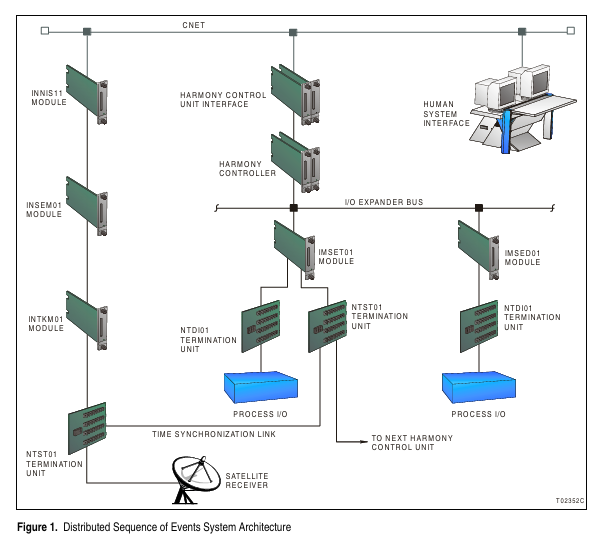
Harmony Sequence of Events (SOE) is for Symphony ™ The distributed event monitoring, recording, and reporting system provided by the enterprise management and control system is mainly used to capture the state transitions of digital signals from on to off or from off to on (SOE events), collect and timestamp these events through a series of SOE modules, and provide event data support for the system.
System architecture and core components
Server Node (INSOE01 Server Node)
INNIS11 Network Interface Module: As the front-end of all Cnet (control network) communication interfaces, it is an intelligent link between nodes and Cnets.
INSEM01 event sequence main module: communicates with INNIS11 and INTKM01 modules, responsible for managing the distributed event sequence system, including processing 1500 points from up to 1000 Harmony control units (HCUs), 256 complex triggers (each containing 16 operands), and 3000 simple triggers; Configure through specific function codes (FC 243-246) to monitor Harmony control unit data based on anomaly reports, collect and organize data, and provide SOE data to the human-machine interface after triggering conditions are met.
INTKM01 time synchronization main module: provides time information to the INSEM01 module and other parts of the distributed SOE system through a time synchronization link, connects to an external receiver using an IRIG-B time code link, and transmits absolute time using an RS-485 time synchronization link; Connect the external receiver signal and time synchronization link through the NTST01 terminal unit.
I/O module
IMSET01 event sequence timing module: processes up to 16 digital field inputs, receives and decodes time synchronization link information sent by INTKM01 module; The controller interacts and configures data with the module through specific function codes (FC 241, 242), with each channel optically isolated and individually programmable to support multiple input voltages; Communicating with the Harmony controller through the I/O expansion bus, only one module can run on one I/O expansion bus segment, connecting the NTST01 and NTDI01 terminal units, responsible for the time synchronization link and on-site wiring terminals, respectively.
IMSED01 event sequence digital input module: similar to IMSET01, but only processes up to 16 digital field inputs and does not handle time synchronization link information; The controller is configured and accesses its input channels through FC 242 function codes. One I/O expansion bus segment can run up to 63 of these modules and one IMSET01 module, and on-site wiring terminals are implemented through NTDI01 terminal units.
Terminal unit
NTDI01 terminal unit: provides physical connection points for on-site wiring.
NTST01 terminal unit: used for terminal connection of time synchronization link, and also provides relevant connection support for IMSET01 module, etc.
technical specifications
General specification: The module is installed in one slot of the standard module installation unit.
Environmental Specifications
Environmental temperature: 0 ° to 70 ° C (32 ° to 158 ° F)
Relative humidity: 5% to 95% at 55 ° C (131 ° F) (no condensation), 5% to 45% at 70 ° C (158 ° F) (no condensation)
Air quality: non corrosive
Certification and Standards
Compliant with CE marking related directives and standards, such as EN50082-2, EN50081-2, EN61010-1, etc.
Certified by the Canadian Standards Association (CSA) and Factory Mutual (FM), suitable for general (non hazardous) locations and classified as non flammable in specific categories.
Parameters of each module
INSEM01: 16 bit microprocessor, operating at a frequency of 10 MHz; The memory includes 2 Mb RAM, 512 kb ROM, and 512 kb NVRAM.
INTKM01: Operating voltage 5 VDC, ± 5%, typical current 300 mA; 16 bit microprocessor, operating frequency 10 MHz; The communication input and output are IRIG-B (DC level conversion format) and RS-485 time synchronization (62.5 kbaud).
IMSED01/IMSET01: Operating voltage+5 VDC, ± 5%, typical current 350 mA; 16 bit microprocessor, operating frequency 10 MHz; The memory includes 64 kb RAM and 64 kb ROM; Digital input supports multiple voltages, with corresponding parameters such as on/off voltage and current. The response time varies depending on the type, and it has certain isolation and surge protection capabilities.


_001_small_1200x630.jpg%3fsfvrsn%3d699670c_0&ehk=DC9Qq12FiwDC7qBWNwnlUPgannRttThr4DlbUnCA9Os%3d&risl=&pid=ImgRaw&r=0)