Call us 24/7uaedcs@163.com
Welcome to the official website of CNIACS Automation Technology Co., Ltd!
Call us 24/7uaedcs@163.com

ABB AC 800M 6.0 Controller Hardware

Product overview

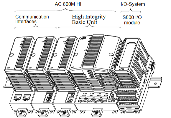
Positioning: AC 800M 6.0 is a high-performance modular controller hardware platform that can achieve various process and industrial automation control functions through programming. It is suitable for various industrial scenarios and can serve as an independent controller or undertake local control tasks in the control network.

Core composition: It consists of hardware components such as processor unit, communication interface, power supply unit, battery backup unit, etc. Some high integrity systems also require special modules such as SM810/SM811/SM812.

Hardware components and functions

Processor Unit

Category: Including PM851/PM851A、PM856/PM856A、PM858、PM860/PM860A、PM861/PM861A、PM862、PM864/PM864A、PM865、PM866/PM866A、PM867、PM891  There are differences in performance and configuration among different models, such as PM891 using MPC8270 microprocessor with a running speed of 450MHz, which is about three times the performance of PM864.

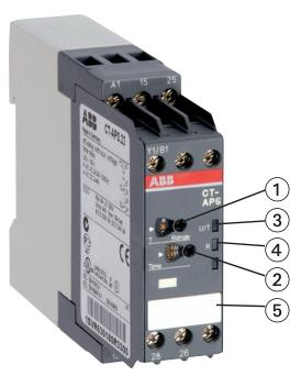
Function: Includes microprocessor, RAM memory, real-time clock, LED indicator lights, initialization button, etc., responsible for running firmware and application programs, and controlling the operation of the entire system. Support redundant configuration, with a primary backup switching time of less than 10ms, and the process output remains frozen during switching.

Communication interface

Diverse types: including RS-232C(CI853)、PROFIBUS DP(CI854/CI854A/CI854B)、MasterBus 300(CI855)、S100 I/O(CI856)、INSUM(CI857)、DriveBus(CI858)、FOUNDATION Fieldbus HSE(CI860) Multiple interfaces are available to expand the communication capabilities of the processor unit, supporting different protocols and device connections.

Function: Implement communication between the controller and external devices, networks, such as connecting remote I/O, fieldbus instruments, drivers, etc.

Power and battery backup

Power supply units, such as SD831, SD832, SD833, SD834, etc., are switch mode power converters that convert AC or DC inputs into stable 24V DC outputs. They support redundant configurations and need to be used in conjunction with voting units (such as SS823, SS832).

Battery backup: includes internal batteries (some models) and external batteries (SB821, SB822), used to provide backup power for memory and real-time clock in case of power failure. SB822 is a rechargeable lithium battery, while PM891 only supports external battery backup.

Other Components

CEX Bus interconnect units, such as BC810 and BC820, are used to divide CEX Bus into independent segments, improve system availability, and support redundant communication interfaces.

SM modules: SM810, SM811, SM812 are used for intelligent monitoring of high integrity controllers. SM811 and PM865, SM812 and PM867 can form a 1oo2 structure, supporting SIL3 applications respectively.

Technical Parameter

Processor performance: Different models of processors have different microprocessor models, operating frequencies, memory capacities, etc. For example, PM864/PM865 uses the 96MHz MPC862 microprocessor, while PM891 uses the 450MHz MPC8270 microprocessor.

Communication capability: Supports multiple communication protocols and rates, such as PROFIBUS DP supporting 9.6kbit/s-12000kbit/s, Ethernet ports supporting 10/100Mbit/s, etc.

Power parameters: The input voltage range, output voltage, and rated current of the power supply vary. For example, the SD831 has an input of 100-240V AC or 110-300V DC and an output of 24V DC/3A.

Environmental parameters: working temperature, storage temperature, humidity, etc. The working temperature range is usually -25 ° C to+60 ° C (some models may vary), and the relative humidity is 5% -85% without condensation

ABB Panel 800 Version 6 Series Operator Panel

Product overview

The Panel 800 Version 6 series is a user-friendly, intuitive, and ergonomic operator panel designed to be compact, space saving, and equipped with advanced features. It supports process and equipment control through function keys next to the screen or touch LCD display screens, making it suitable for process monitoring and operation in industrial automation scenarios.

Product classification and core parameters

This series is divided into three categories: standard panels, high-performance panels, and reinforced panels. The specific models and parameters are as follows:

Category, Model, Display Screen Size, Resolution and Proportion, Core Configuration Size (W × H × D, mm), Protection Level (Front/Rear), Operating 

Temperature Range

Standard panel PP871 4.3 “480 × 272 (16:9) ARM9 processor (400MHz), 128MB memory 145 × 103 × 49 IP66/IP20-10~+60 ° C

PP874 7 “800 × 480 (16:9) Same as above 204 × 143 × 49 IP65/IP20 Same as above

PP877 10.4 “640 × 480 (4:3) Same as above 280 × 228 × 51 Same as above

PP874K/PP877K 7 “/10.4” with button operation as above, other models are slightly larger than PP874/PP877 and the same as above

High performance panel PP882 12.1 “1280 × 800 (16:10) Intel Atom processor (1.1GHz), 1GB memory 340 × 242 × 79 IP65/IP20-10~+50 ° C

PP885 15.4 “Same as above 410 × 286 × 83 Same as above

Reinforced panel PP880R 7 “800 × 480 (16:9) 1.0GHz Intel Atom, 3.5GB storage 204 × 143 × 73 IP66/IP20-30~+70 ° C

PP885R/PP886H 15.4 “1280 × 800 (16:10) 1.0/1.6GHz Intel Atom 410 × 286 × 83 Same as above

Common parameters:

Interaction mode: resistive touch (million touch cycles) or button operation (million press cycles).

Interface: All are equipped with Ethernet (RJ45), USB 2.0, RS232/RS422/485 serial ports, and support SD card expansion storage.

Power supply: 24VDC (18-32VDC), power consumption varies from 3.6W to 28W depending on the model.

Communication function

Supports multiple industrial communication protocols and drivers, and can be integrated with mainstream PLCs and control systems, including:

ABB proprietary protocols: COMLI (master/slave), Control Network MMS, Freelance 2016, etc.

Universal protocols: Modbus (ASCII/RTU/TCP, master/slave), Profinet, Ethernet/IP, OPC DA/UA, etc.

Third party agreements: Siemens S7 series, Schneider Uni Always, Rockwell DF1, etc., covering nearly 50 types of drivers.

ABB System proS series enclosed starter

Product Overview

Series positioning: System proS enclosed starters include direct online (D.O.L.) starters and dual speed starters, including non combination and combination types, suitable for 1-phase and 3-phase motor control, with a maximum CSA/UL horsepower rating of 7.5 to 125HP at 600VAC.

Core features: Compact and space saving design, pre wired indicator light components and control transformer kit for easy on-site modification and installation, anti misoperation design for terminals, all connection terminals can prevent accidental contact, and necessary terminal blocks and wiring are also included. The starter can be controlled through external holding contacts.

Starter type and specifications

1-phase starter

Non combination: Divided by contactor size (AF09, AF16, AF30, AF52, AF80), corresponding to different CSA motor switch currents and maximum motor horsepower ratings (120V and 240V), and providing models of different housing types (Type 1, Type 4/12, Type 4X).

Combination type: including types of fuse isolation switches and non fuse isolation switches, also divided according to the size of the contactor, corresponding to different motor parameters and housing models.

3-phase starter

Non combination type: There are types such as irreversible, reversible, and dual speed (2 windings and 1 winding), divided according to the size of the contactor (AF09, AF16, AF30, AF52, AF80, AF140), corresponding to the maximum motor horsepower rating at different voltages, and providing models of different housing types.

Combination type: including types of fuse isolation switches, non fuse isolation switches, and MCP circuit breakers, divided by contactor size, corresponding to different motor parameters and housing models.

Core parameters and selection

Coil voltage: Provides multiple options such as 24-60V, 48-130V, 100-250V, 250-500V, etc., which can be distinguished by the last digit of the catalog number.

Overload relay: Class 10 adjustable overload relay is used, and different contactor sizes correspond to different models of overload relays. The current setting range and cable range are different, and the selection should be based on the motor parameters.

Catalog number explanation: The number includes information such as housing type, combination method, starter type, contactor size, coil voltage, overload selection, indicator light components, auxiliary contacts, etc. The specific model can be determined according to the needs.

Attachment

Indicator light components: There are various types, including combinations with buttons and indicator lights, switches and indicator light combinations in different positions, etc., which can be installed by customers or factories. They are suitable for different types of starters and come in versions such as 130V and 24V, with different functions and identifications.

Transformer kit: Divided by contactor size and VA rating, there are options such as 50VA and 100VA. The input (primary) voltage ranges from 120-600V, and the output (secondary) voltage is 24V and 120V. It can be factory installed.

Technical data and installation

Technical parameters: Main protection, contactor, maximum overload, combined short-circuit current, AC1 and AC3 rated current, and corresponding horsepower of single-phase and three-phase motors for different types of starters.

Size specifications: Dimensions (height, width, depth) of starters of different types (non combination, combination) and different housing types (Type 1, Type 4/12, Type 4X).

Electrical diagram: including electrical wiring diagrams for direct online starters, single-phase 2-pole starters, reversible starters, dual speed 2-winding starters, etc., as well as electrical diagrams for indicator light components.

ABB Tmax T7 series molded case circuit breaker

Product Overview

Series positioning: The Tmax T7 series is a high current model in ABB molded case circuit breakers, covering a current range of 630A-2500A, designed to meet the needs of high reliability, high breaking capacity, and compact design in industrial distribution systems.

Product types: including distribution circuit breakers (with thermal magnetic or electronic release), motor protection circuit breakers, etc., suitable types can be selected according to different application scenarios.

Core technical parameters and performance

Breaking capacity: At 480V AC voltage, the breaking capacity can reach 150kA, which can effectively deal with short-circuit faults and ensure system safety.

Release type:

Thermomagnetic release: Provides overload and short circuit protection, with relatively fixed parameter settings, suitable for conventional protection scenarios.

Electronic release devices (such as PR231/P, PR232/P, etc.): have more precise protection functions, support multiple protection curves, and can provide precise protection against overload, short circuit, grounding faults, etc. Some models also support communication functions (such as Modbus RTU), making remote monitoring and management easier.

General parameters: protection level IP54, insulation level F, temperature rise level B (some models are F), operating temperature range -25 ℃ to+70 ℃, storage temperature -40 ℃ to+70 ℃, in compliance with multiple international standards such as IEC 60947-2.

Installation and Configuration

Installation method: Supports fixed installation, plug-in installation, and pull-out installation. Multiple installation methods can meet different cabinet design and maintenance needs. Some models can be converted to different installation methods through conversion kits.

Connection method: Provides multiple terminal types, including front wiring, rear wiring, multi cable terminals, etc., suitable for copper and aluminum cables, making it easy to connect with different lines.

Accessories: Equipped with a variety of accessories such as auxiliary contacts, undervoltage release, shunt release, remote control mechanism, residual current release, etc., the circuit breaker function can be expanded according to actual needs.

Application and Authentication

Application scenarios: Widely used in industrial power distribution systems, large building power distribution, energy industries, and other fields, it can be used for main power distribution, feeder line protection, and protection of large motors.

Certification: Compliant with multiple international standards such as UL 489, CSA C22.2, IEC, and some models have been certified by classification societies (such as ABS, RINA, etc.) to ensure the applicability of the product in different regions and industries.

ABB UK 500 series household distribution box

Product Overview

Design concept: Integrating years of market experience and innovative design, balancing technical performance and decorative appeal, meeting high standards of functionality and aesthetic needs. The white standard version adopts modern design and is suitable for various decoration styles.

Core advantages: Easy installation (single handed cable operation, quick snap fastener fixation, etc.), high flexibility (supporting multiple installation methods and extensions), strong security (complying with multiple standards).

Structure and installation characteristics

Box design:

Made of non warped, drop resistant, and non combustible plastic material (compliant with UL 94-V2 standard), with a large internal space and equipped with cable strain relief comb. There are pre formed cable entrances on the side and back.

Wall mounted grip is a standard configuration that can reduce installation depth or serve as a spacer for multiple distribution boxes installed side by side. It can be flipped to provide two insertion depths.

Installation method:

Support embedded installation, hollow wall installation can be achieved through the UZ 90 E hollow wall installation kit, without the need for a dedicated distribution box.

The equipment bracket adopts a snap on system, which can be quickly installed without tools. The DIN rail is double insulated, and the N/PE terminals and N-RCD terminals are plug-in. All clips comply with VBG 4 standards to prevent accidental contact.

Cover plate and door frame:

The cover plate is fixed with two 900 quick action locking screws, which can be sealed, and the slot width can be expanded from 12 modules to 14 modules.

The decorative frame and door are easy to disassemble and can adapt to uneven surfaces.

Product series and models

Basic version: No decorative frame and door, including box body, equipment bracket, movable DIN rail, cover plate, N/PE terminal, N-RCD clamp terminal, wall clamp, label system, etc. It is divided into four types according to module width: 12 (14), 24 (28), 36 (42), 48 (56), corresponding models are UK 510 BE, UK 520 BE, UK 530 BE, UK 540 BE, and the dimensions (HxWxD), niche dimensions, wall cut dimensions, and weight are given respectively.

Standard version and options: with decorative frame and door, there are various styles of decorative frame and door, such as:

Standard version: Alpine white (RAL 9003) powder coated steel plate material.

Art line “: Made of brushed stainless steel material.

“Additional line”: Photo frame doors made of brushed aluminum or coated with anodized color.

Color line “: There are metal coatings such as Bordeaux red, anthracite, midnight blue, etc.

Transparent door design.

Different styles are compatible with different base models and have corresponding internal and external dimensions.

control panel:

The front-end control panel can be used to monitor and operate building functions (such as lighting systems), using standard UK 500 components, with a sturdy aluminum frame and anodized front panel and safety lock.

There are three models (FPT 510 E, FPT 520 E, FPT 530 E) with different external dimensions, which can be decorated by the user or pre installed and printed by the factory.

Accessories and replacement parts

Including enclosure, wall clamp, quick action screws, hollow wall installation kit, surface installation kit, N and PE terminals, N-RCD terminals, labeling system, cable ties, screws, mounting plates, snap closures, safety locks, slot covers, cable entrances, vertical and horizontal partitions, etc., the product models that each accessory is compatible with are listed in detail.

Technical Standards and Certification

Compliant with DIN VDE 0603, DIN 43

871, German Institute of Engineers standard VDE 0100/729, etc., with an IP protection level of IP 30 and a rated current of 63A.

image.png

ABB contactors and overload relays

Product Series Overview

The document covers multiple contactor and overload relay series under ABB, with core products including:

Contactor:

AX series: suitable for low-voltage distribution and motor control, with a current range of 6A-1000A, supporting AC/DC coils, featuring compact design and high mechanical life (≥ 10 million cycles).

AF series: designed for frequent operation scenarios such as elevators and cranes, with a current range of 9A-400A and a mechanical lifespan of up to 30 million cycles.

A-series: Classic series, covering 12A-630A, supports multiple coil voltages, and is compatible with global standards.

Overload relay:

TA series: Thermal overload relay, used in conjunction with contactors, with a current range of 0.1A-630A, providing manual/automatic reset function.

TF series: Electronic overload relay with precise protection (overload, phase loss, locked rotor, etc.), supporting communication functions (such as Modbus), current range of 0.1A-800A.

Combination product: Pre assembled units for contactors and overload relays (such as AX+TA, AF+TF), simplifying selection and installation.

Core technical parameters and performance

Key indicators of parameter categories

Electrical performance – rated voltage: AC below 690V, DC below 250V (some models support higher voltages).

-Breaking capacity: It can reach 10 times the rated current under AC-3 load (such as AX18 with a breaking capacity of 100A at 400V).

-Coil power consumption: AC coil ≤ 15VA, DC coil ≤ 10W, energy-saving coil power consumption reduced by more than 50%.

Mechanical performance – Operating frequency: up to 1200 times/hour (AX series), AF series supports higher frequencies (such as 3600 times/hour).

-Protection level: The contactor body is IP20, and after installing a casing, it can reach IP65.

-Installation method: DIN rail installation (35mm) or screw fixation, supporting vertical/horizontal installation.

Protection Function – Overload Relay: The TA series achieves overload protection through bimetallic strips, while the TF series has an electronic trip curve (Class 10/20/30) and customizable protection parameters.

-Contactor: equipped with an arc extinguishing cover to reduce damage to the contacts caused by the arc, and supports reversible control (through mechanical interlocking).

Environmental adaptability – Operating temperature: -25 ° C to+70 ° C (some models -40 ° C to+70 ° C).

-Vibration resistance: 10-55Hz, amplitude 0.75mm; Impact resistance: 30g (11ms).

Selection and Application Guide

Selection criteria: Select the model based on the load type (motor, lighting, electric heating, etc.), rated current, operating frequency, protection requirements (overload, short circuit, etc.), and environmental conditions (temperature, humidity). The document provides a detailed selection table, including the current matching relationship under different load types (such as AC-1 resistive load, AC-3 motor load).

Typical application scenarios:

Industrial motor control (pumps, fans, conveyors).

Low voltage distribution system (distribution box, switchgear).

Building automation (air conditioning, elevators).

Renewable energy sources (photovoltaic inverters, wind power converters).

Installation and maintenance

Installation points:

Wiring: The main circuit uses copper or aluminum cables (with copper aluminum transition terminals), and the cross-sectional area of the control circuit wires is 0.5-2.5mm ², with a tightening torque of 0.5-2.5Nm (depending on the terminal specifications).

Spacing requirement: Contactors of different current levels must maintain a certain electrical clearance (such as 100A or above ≥ 15mm) to ensure heat dissipation and insulation.

Maintenance suggestion: Regularly check contact wear (replace when thickness ≤ 1mm), clean the arc extinguishing cover, test the accuracy of overload relay action, and avoid long-term operation in dusty and corrosive environments.

Certification and Standards

Compliant with international standards: IEC 60947-1/4 (contactors), IEC 60947-5-1 (overload relays).

Certification coverage: CE, UL, CSA, CCC, GL (Classification Society), etc., applicable to the global market.

Additional Information

Provide technical charts such as product size diagrams, wiring diagrams, trip curves (overload relays), and lifespan curves to assist in installation and debugging.

Contains environmental information: The product materials comply with the RoHS directive, and the proportion of recyclable parts is ≥ 90%.

Emphasize safety reminder: Installation should be operated by professional electricians, and maintenance should be carried out after power failure to avoid electric shock or mechanical injury.

ABB NTAC-0x pulse encoder interface module

Safety instructions

Warning types: including dangerous voltage warning, general warning, electrostatic discharge warning, reminding users to have professional electricians perform electrical installation and maintenance. Drivers and related equipment must be properly grounded. After power failure, wait for 5 minutes for the intermediate circuit capacitor to discharge, and use voltage indicating instruments to confirm the completion of discharge. At the same time, be aware of the risks that may arise from the automatic reset function of the driver.

Attention: Emphasize following the manufacturer’s operating instructions to avoid hazards such as electric shock.

Overview

Scope of application: Applicable to NTAC-02 (revised version C and above), NDIO-02 (revised version A and above), NAIO-03 (revised version A and above), and includes reference information from earlier versions (NTAC-01, NDIO-01, NAIO-01/02).

Module function:

NTAC-02: Provides a digital pulse encoder interface for obtaining precise speed or position feedback of the motor shaft.

NDIO-02: Provides 2 digital inputs and 2 relay outputs.

NAIO-03: Provides 2 analog inputs and 2 analog outputs, with signal resolution (12 bits) superior to standard analog I/O.

Communication link: Connected to the frequency converter through an optical DDCS protocol communication link, the module and NIOC standard I/O board usually form a circular connection on the CH1 channel of the NAMC board, which acts as the main station to cyclically poll other stations.

install

Module Node Number Setting: Different modules (NTAC, NDIO, NAIO) have their own node numbering rules set through DIP switches inside the module casing. The new settings will take effect when the module is powered on next time.

Mechanical installation: It can be installed inside or outside the drive. When installing outside, attention should be paid to wiring, space, environmental conditions, and grounding requirements. When installing inside, it should be operated by a professional electrician, following steps such as power-off, discharging, and removing the cover plate.

ACS 600 connection: Use fiber optic cables to connect to the NAMC/NDCO board of the driver, paying attention to the color coding of the connectors (blue for RXD, gray/black for TXD). Multiple modules are connected in a circular manner on the same channel, and the terminals connected to different modules vary depending on the application.

Detailed installation and configuration of each module

NTAC-02 pulse encoder interface module: introduces terminal identification, current consumption, wiring requirements (cable type, length, shielding grounding, etc.), encoder output type connection diagram (push-pull, collector open circuit, emitter open circuit), and programming method (set through driver parameters).

NDIO-02 digital I/O expansion module: including terminal identification, wiring recommendations, DI1 hardware filter suppression settings, and programming methods (activating communication through driver parameters).

NAIO-03 Analog I/O Expansion Module: Includes mode selection (unipolar/bipolar), input signal type selection (current/voltage), terminal identification, wiring requirements, programming methods (activates communication through driver parameters to ensure parameter settings correspond to module mode switches).

Appendix Information

Technical data: including detailed technical parameters such as I/O expansion links, enclosure of each module, installation, connectors, input and output.

Environmental conditions: lists the environmental requirements for temperature, humidity, vibration, impact, etc. of the module during operation, storage, and transportation.

Early version information: Introduces the differences, terminal identification, settings, and other information between NTAC-01, NDIO-01, NAIO-01/02 and their corresponding new versions.

​Install and start ABB NTAC-0x module

Installation preparation

Confirm compatibility

The module needs to be used in conjunction with the ACS 600 series frequency converter, and the application version must be ≥ V5.0 (standard application) or ≥ V4.2 (system application).

Check the encoder type (push-pull, open collector or open emitter) and prepare matching connecting cables.

Safe power outage

Disconnect the main power supply of the frequency converter and wait for 5 minutes until the intermediate circuit capacitor discharges completely.

Use a voltage indicator to confirm that there is no residual voltage.

Physical installation steps

1. Node number setting

Open the module casing and set the node number (range: 1-31) through the DIP switch.

Rule:

The NTAC module number needs to be an even number (such as 2, 4, 6…).

Node numbers within the same channel cannot be duplicated.

After the setting is completed, it will take effect when powered on again.

2. Mechanical installation

Internal installation (recommended):

Remove the cover plate of the frequency converter and insert the module into the CH1 channel of the NAMC board or NDCO board.

Connect the RXD (blue interface) and TXD (gray/black interface) of the module using fiber optic cables to form a circular topology.

External installation:

Choose a dry and ventilated location to ensure that the ambient temperature is between -25 ° C and+55 ° C.

Fix the module with M4 screws and maintain a minimum spacing of 50mm.

3. Encoder connection

Select the corresponding terminal based on the encoder type (such as A+/A -, B+/B -).

Wiring requirements:

Use shielded cables with both ends of the shielding layer grounded.

The encoder cable should be kept at least 100mm away from the power cord to avoid interference.

Maximum cable length: push-pull encoder ≤ 100m, differential encoder ≤ 300m.

Electrical connection

1. Power connection

The module is powered internally by the frequency converter and does not require additional power supply.

2. Fiber optic communication connection

Connect the RXD (receiver) of the module to the TXD (transmitter) of the previous node to form a circular link.

The TXD of the last module needs to be connected back to the NAMC board or NDCO board of the frequency converter.

3. Encoder signal connection

Push pull encoder: directly connected to the digital input terminal of the module.

Differential encoder: Connected after conversion by a differential receiver.

Troubleshooting

communication failure

Check if the fiber optic connection is secure and if the interface is clean.

Confirm that there are no conflicts in the node numbers and that all module numbers are even.

Encoder signal loss

Check if the encoder power supply is normal (usually+5V or+24V).

Use an oscilloscope to check if the encoder output waveform is stable.

Parameter not effective

Restart the frequency converter and ensure that the parameters are saved to non-volatile memory.

Precautions

Static protection: Wear an anti-static wristband before operation to avoid touching the circuit board.

Environmental requirements: Avoid installation in damp, dusty, or strong electromagnetic interference environments.

Maintenance: Regularly clean the module’s heat dissipation holes and check for dust or damage to the fiber optic interface.

ABB electronic timer CT-APS.22

Basic characteristics of the product

Function: Single function delay shutdown timer with 2 conversion contacts (2 c/o contacts).

Power supply voltage: Supports 24-48 V DC and 24-240 V AC.

Time Range: 10 time ranges are available, covering 0.05 s to 300 h. The time range can be pre selected by rotating the switch, and the front-end potentiometer has a direct reading scale for fine adjustment.

Status indication: 2 LED indicator lights, green LED (U/T) displays the control power supply voltage application and timing status (flashing during timing), yellow LED (R) displays the output relay power status.

Size: Width 22.5 mm, compact design.

Protection function: Optional sealable transparent cover (COV.01) to prevent unauthorized changes to time values; Integrated Tag Label (MAR.01).

Certification: Passed UL 508, CAN/CSA C22.2 No.14, GL, GOST, CB scheme, CCC and other certifications, with CE and C-Tick marks.

Working mode and function

Delay shutdown function: Continuous control of power supply voltage timing is required. When the control inputs A1-Y1/B1 are closed, the output relay is immediately powered on; When the input is disconnected, there is a delay and the green LED flashes; After the delay is over, the output relay will be powered off and the green LED will remain on. If the input closes again before the delay ends, the delay will reset and the output relay status will remain unchanged; When the control power supply is interrupted, the output relay will be powered off and reset with a delay.

Terminal description: The first conversion contact is 15-16/18, the second is 25-26/28, the control power is connected to A1-A2, and the control input is A1-Y1/B1.

Technical Parameter

Input circuit:

Control power supply voltage tolerance: 24-48 V DC is -15…+10%, 24-240 V AC is -15…+10%.

Typical current/power consumption: 16 mA at 24 V DC, 60 mA at 24-48 V DC (as needed), 36 mA at 115 V AC (as needed), etc.

Frequency range (AC): 47-63 Hz.

Power failure buffer time: 24 V DC minimum 15 ms, 230 V AC minimum 20 ms.

Control circuit: The control input is voltage dependent trigger, anti reverse polarity, non polarized, switchable parallel load, maximum cable length of 50 m (100 pF/m), minimum control pulse length of 20 ms, control input current of 1.2 mA at 24 V DC and 8 mA at 230 V AC.

Timing circuit: Recovery time<80 ms, repeatability accuracy (constant parameter) Δ t<± 0.2%, accuracy within voltage tolerance Δ t<0.004%/V, accuracy within temperature range Δ t<0.03%/° C.

Output circuit: rated working voltage of 250 V, minimum switching voltage/current of 12 V/10 mA, AC rated working current (IEC/EN 60947-5-1) AC12 (230 V, resistive) 4 A, AC15 (230 V, inductive) 3 A, DC rated working current DC12 (24 V, resistive) 4 A, DC13 (24 V, inductive) 2 A; mechanical life of 30 × 10 ⁶ switching cycles, electrical life (AC12230 V, 4 A) 0.1 × 10 ⁶ times; The maximum rated value of the short-circuit protection fuse is 6 A for normally closed contacts and 10 A for normally open contacts.

General data: Duty cycle 100%, dimensions (width x height x depth) 22.5 × 78 × 100 mm, weight 0.128 kg, installation position arbitrary, minimum distance from other equipment not required during normal operation, installed on DIN rail (IEC/EN 60715), enclosure/terminal protection level IP50/IP20.

Electrical connection: Screw connection, wire specification (fine stranded wire with wire end sleeve) 2 × 0.75-2.5 mm ² (2 × 18-14 AWG), wire stripping length 7 mm, tightening torque 0.6-0.8 Nm.

Environment and Isolation Data

Environmental data: working environment temperature -25…+60 ° C, storage environment temperature -40…+85 ° C, withstand 6 × 24-hour cycles of humidity and heat (55 ° C, 95% RH); The tolerance to vibration, impact and other environmental factors meets relevant standards.

Isolation data: rated insulation voltage of output circuit 300 V, input/output circuit 500 V; power frequency withstand voltage test (routine/type) 2.0 kV (50 Hz, 1 s)/2.5 kV (50 Hz, 1 min); Basic insulation (input/output) 500 V, protective isolation 250 V; pollution level 3, overvoltage category III.

Standards and Compatibility

Compliant with product standards such as IEC 61812-1, EN 61812-1+A11, as well as directives such as EMC, low voltage, RoHS, etc.

In terms of electromagnetic compatibility, both anti-interference and interference emission comply with relevant standards and level requirements.

ABB Small, compact Thermostat KTO 011 / KTS 011

Basic Product Information

KTO 011: Normally closed thermostat, which can be used as a contact circuit breaker for heaters.

KTS 011: Normally open thermostat, which can be used to adjust the contact closure of filter fans and heat exchangers, or switch signal devices when the temperature exceeds the limit.

Features: Large setting range, small size, easy installation, high switch performance.

Technical Parameter

Switch temperature difference: 7K (tolerance ± 4K)

Sensor element: Thermostatic bimetallic strip

Contact type: Quick acting contact

Contact resistance:<10mOhm

Service life:>100000 cycles

Maximum switch capacity: 250VAC, 10 (2) A; 120VAC,15(2)A; DC 30W

Electromagnetic compatibility: compliant with EN 55014-1-2, EN 61000-3-2, EN 61000-3-3 standards

Connection method: 2-pole terminal, suitable for 2.5mm ², clamping torque 0.8Nm

Installation method: Suitable for clamp on 35mm DIN rail (EN50022) or for EF 118 series outlet filter

Shell: UL94 V-0 grade plastic, light gray

Size: 60 × 33 × 43mm

Weight: Approximately 40g

Installation location: Variable

Working/Storage Temperature: -20 to+80 ° C (-4 to+176 ° F)/-45 to+80 ° C (-49 to+176 ° F)

Protection level:IP20

Model and certification information

The models and certifications corresponding to different setting ranges are shown in the following table:

Setting range, normally closed (NC) model, normally open (NO) model, certification:

0 to+60 ° C, 01140.0-00, 01141.0-00, VDE

-10 to+50 ° C, 01142.0-00, 01143.0-00, VDE

+20 to+80 ° C, 01159.0-00, 01158.0-00, VDE

+32 to+140 ° F, 01140.9-00, 01141.9-00, UL File No. E164102

+14 to+122 ° F, 01142.9-00, 01143.9-00, UL File No. E164102

0 to+60 ° C, 01146.9-00, 01147.9-00, UL File No. E164102

Installation and Commissioning

Installation related basic information

Installation method: It can be installed using clips suitable for 35mm DIN rails (compliant with EN50022 standard), or it can be installed on the EF 118 series outlet filter.

Connection method: Using 2-pole terminals, suitable for 2.5mm ² wires, with a clamping torque of 0.8Nm.

Installation position: Flexible selection, not fixed position.

Debugging related tips

Due to the lack of clear debugging steps in the document, combined with the general usage logic of thermostats, the following aspects can be focused on during debugging:

Temperature setting: Adjust the temperature threshold within the specified setting range of the product according to actual needs (different models have different setting ranges, such as 0 to+60 ° C, -10 to+50 ° C, etc.).

Functional testing: By changing the ambient temperature, observe whether the switch status of the thermostat meets expectations (KTO 011 is normally closed and opens when the set temperature is reached); KTS 011 is a normally open type that closes when the set temperature is reached to verify its proper functioning.

ABB low-voltage AF contactor AF400… AF460

Product overview

Product positioning: ABB’s AF contactor series is a benchmark product in the industry. Its integrated electronic control coil has multiple advantages compared to traditional products, and combined with ABB’s rich product portfolio, it can achieve the optimization of each configuration.

Scope of application: AF400… AF460 three pole contactors are designed to control motors ranging from 200 to 250 kW (AC-3) at 400V AC or 250 to 400 hp at 480V AC UL, as well as switch power circuits up to 700A (AC-1) or 650A UL/CSA universal.

Product features:

Using AF technology, the control voltage range is wide (48… 500V 50/60Hz and 24… 500V DC), and only 4 coils are needed to cope with large control voltage changes, reducing panel energy consumption and ensuring stable operation in unstable networks.

Built in PLC control and surge protection, the solution is compact.

Adopting a block design, it is easy to expand additional auxiliary contact blocks and various accessories.

Product compliance

REACH regulation: AF contactors and related accessories are classified as articles and will not intentionally release any substances or preparations under normal and reasonably foreseeable conditions of use. ABB continues to communicate with the supply chain and collect information on suppliers’ compliance with REACH regulations.

SVHC substances: ABB continuously evaluates the content of highly concerned substances (SVHC) in its products. As far as we know, the content of SVHC substances in AF contactors and related accessories does not exceed 0.1% by weight.

RoHS II Directive: AF contactors and related accessories fall within the scope of the 2011/65/EU Directive (RoHS II) and its 2015/863 amendments, and are applicable from July 22, 2019.

WEEE Directive: Compliant with the 2012/19/EU Directive of the European Community on Waste Electrical and Electronic Equipment (WEEE Directive).

Product Safety

Ensure basic health and safety requirements are met by complying with applicable product and safety standards.

The third-party testing laboratory (STIEE/TL030) has conducted product and safety standard validation in accordance with EN ISO/IEC 17025 European standards and the IECEE CB program, and has issued a CB certificate.

Material Declaration

Taking AF460-30-11-70 (representing AF400… AF460 series contactors) as an example, the total weight is 9621 grams, and its composition materials and proportions (weight percentage) are as follows:

Proportion of materials

Steel: 51.2%

Copper: 8.5%

BMC:24.9%

Precious metals: 0.1%

PA:8.4%

SMC:4.0%

PCBA:1.0%

FRP:0.9%

PBT:0.7%

HNBR:0.1%

POM:0.1%

FKM:0.02%

Total: 100.0%

Packaging

Taking AF460-30-11-68 as an example, the total weight of the packaging is 205 grams, and the material composition and proportion are:

Cardboard: 72%

Plastics: 28%

Total: 100%

Among them, the cardboard and paper used for product packaging are made of recycled fibers and are 100% recyclable; The polymer film used is labeled with an appropriate identification code and is recyclable.

Search for products

Back to Top
Product has been added to your cart