DANAHER MOTION 60MB1296DU-18Y (also written as 60MB1296DU18Y) is a product with important application value in industrial automation and other fields. It is built with new manufacturing processes and technical standards, dedicated to providing stable and efficient operational support for related equipment. From precision instruments to large industrial machinery, it can play a key role with its excellent performance.
Superior Electric is a Danaher Motion brand, and is recognized worldwide as the leading manufacturer of step motor positioning systems. Over 40 years ago, Superior
Electric developed and patented their Superior step motor products.
The Superior Electric family of automation products includes:
• Step Motors
• Step Motor Drives
•Motion Controls
• Synchronous Motors
This catalog highlights the latest selection of high torque step motors from Superior Electric.
Our new line of NEMA size 42 high torque motors complements and extends the range of our size 23 and 34 high torque motors.
These high torque motors provide world-class performance, and represent the best value ever offered by Superior Electric.
They provide twice the torque (and in some cases more than twice the torque) of older conventional step motors.
Introduction To Step Motors
Superior Electric step motors provide very precise, cost effective, motion control.
Superior step motors inherently move in small, very precise, 1.8° increments (200 / revolution).
This stepping action is simple to control and does not require complicated, expensive feedback devices.
With micro stepping drives, each 1.8° step can be broken into even smaller increments.
And, if position verification is required, motors are available with encoders.
Due to their ease of use, simplified control needs and freedom from expensive feedback requirements, Superior step motors are excellent alternatives to pneumatic,hydraulic and servo motor systems.
Sizing and Selection Software for Superior Electric Products
Step motor systems are often used in high performance positioning systems.
The correct motor and drive are equally important for the system to meet performance and cost goals.
To select a motor and drive for a given situation requires an analysis of the load, mechanical system and desired cycle times or speeds.
Typical Applications
• Automation and inspection
• Conveyor transfer
• Cut-to-length metal, plastic, fabric, etc.
• Industrial HVAC
•Material handling
•Medical equipment
•Office peripheral equipment
• Packaging systems
• Pick-and-place applications
• Printing systems
• Robotics
• Semiconductor manufacturing
MOTIONEERING® Software for
Superior Electric, makes the selection process easy.
MOTIONEERING® is a menu driven, Windows®-based program that automatically takes into
account load, motor and drive parameters.
A wide variety of mechanisms are accommodated including: lead screw, rack and pinion, conveyor (belt and pulley),nip rolls, and rotary, as well as direct data entry.
MOTIONEERING® provides a versatile environment for choosing the optimum system for your application, and is available free of charge.
Sizing and Selection Software
Step motor systems are often used in high performance positioning systems.
The correct motor and drive are equally important for the system to meet performance and cost goals.
To select a motor and drive for a given situation requires an analysis of the load, mechanical system and desired cycle times or speeds.
MOTIONEERING® Software for Superior Electric, makes the selection process easy.
•Menu driven, Windows®-based program
• Automatically takes into account load, motor and drive parameters.
• Accommodates a wide variety of mechanisms: lead screw,rack and pinion, conveyor (belt and pulley), nip rolls, and rotary, as well as direct data entry
• All common metric and English units can be used; and the program converts data into the other available units
• Application and system data is organized in project folders that can be exported or imported for sharing with other users
• An extensive database of system combinations is incorporated.
These include NEMA size 23, 34, 42, and 66 motors combined with drives having input voltages from 12 VDC to 240 VAC
• On-line help explains the programs functions, terms and equations.
MOTIONEERING® software provides a versatile environment for choosing the optimum step system for your application and is available free of charge.
Characteristics of Superior Electric
Step Motors
•Brushless, permanent magnet motors
• Operate in full-step (1.8°) or half-step (0.9°) increments
•Microstepping provides increments as small as 0.0072°
• Accuracies of ±2% (0.036°) for size 23 and 34 motors, and ±5% (0.09°) for size 42 and 66 motors
• Speeds up to 20,000 steps per second (6,000 rpm)
• Holding torque ratings from 54 to 5,330 oz-in (38 to 3,764 N-cm)
•Wide range of configurations and frame sizes
• Easily adapted to different control types, including microprocessor based systems
• Class B insulation, operate at ambient temperatures from -40°C to +65°C (-40°F to +149°F)
• No brushes, ratchets or detents to wear out
• Lubricated-for-life ball bearings
Servomotor Characteristics
• Require complex, expensive control systems
• Position sensing devices needed for feedback to control
• Relatively low torque for size
• Thermally inefficient
• Control system must be “tuned” to load; must be “retuned” if load is changed
•Brushes on DC servomotors subject to wear Superior Electric Step Motor Characteristics
• Relatively inexpensive
• Can be operated “open-loop” (no position feedback required)
• Noncumulative step error
• Simple control electronics can be used
•Brushless construction aids reliability
•Maintenance free
•Will not be damaged if stalled
• High torque for size
• Maintain position when at rest
Technical Notes (Continued)
Stepping Techniques
The terms full-step, half-step and microstep are commonly used in the discussion of step motors.
A standard 1.8° step motor has 200 discrete positions in a full 360°revolution.
Since 360° divided by 200 equals 1.8°, the motor shaft will advance 1.8° each time the motor is given a digital command to take one step.
This is known as a full-step.
The term “half-step” indicates a 0.9° step angle (half of a full 1.8° step).
This is achieved with a switching technique that alternately applies positive current, no current, and negative current to each winding in succession.
The term “microstep” refers to a more sophisticated form of control which goes beyond the simple switching of power between phase A and phase B of the motor windings, and takes control of the amount of current being sent to the individual windings.
Microstepping permits the shaft to be positioned at places other than the 1.8° or 0.9° locations provided by the full-step and half step methods.
Microstepping positions occur between these two angular points in the rotation of the rotor
The most commonly used microstep increments are 1/5,1/10,1/16,1/32, 1/125 and 1/250 of a full step. Microstep increments chosen by Superior Electric simplify control of both US and metric units of measurement, and also allow finer positioning resolution.
While a full step of 1.8° will give a 0.001 inch resolution when the motor is driving through a lead screw which has a 0.2000 inch lead,resolutions of 0.000008 inch or less are possible using microstepping.
A major benefit of microstepping is that it reduces the amplitude of the resonance that occurs when the motor is operated at its natural frequency or at sub-harmonics of that frequency.
The improved step response and reduced amplitude of the natural resonances result from the finer step angle.
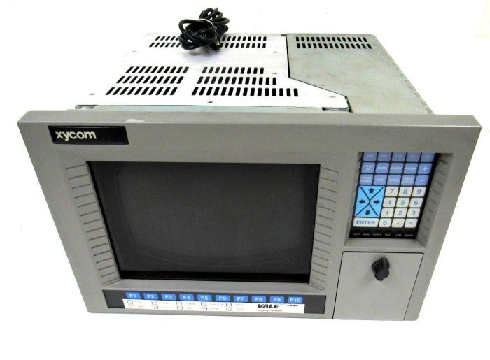
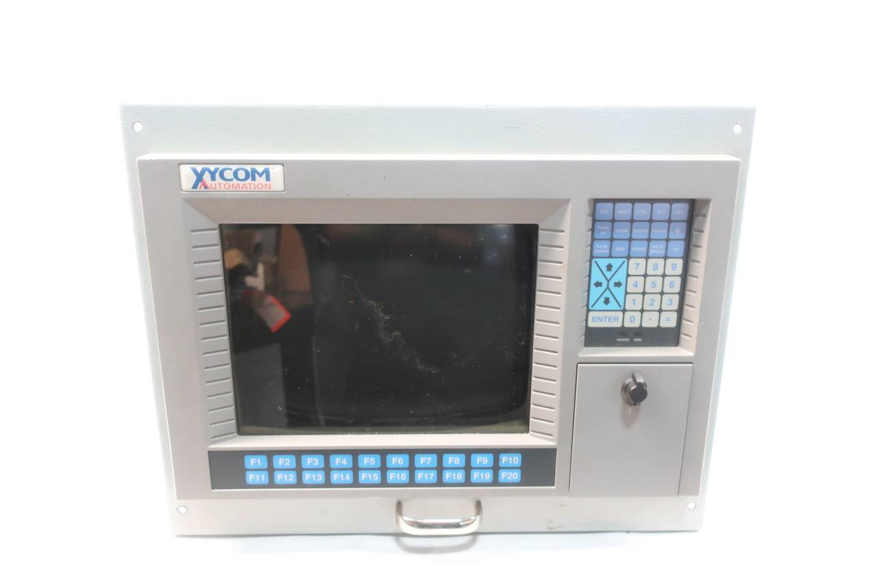
Xycom 9450 Interface Screen Monitor is an industrial grade interface screen monitor that integrates display and interaction functions. It aims to provide industrial operators with an intuitive and convenient human-computer interaction interface, facilitating users to monitor the real-time operation status of industrial equipment, adjust equipment parameters, receive alarm information, etc. This monitor is suitable for various industrial scenarios, such as factory automation production lines, energy management systems, mechanical equipment monitoring, etc. It can seamlessly integrate with multiple industrial control systems and become an indispensable component of industrial automation processes.
Core Features
(1) Display performance
High definition display: Equipped with a high-resolution display screen, the specific resolution can reach [X] × [X] pixels, which can clearly present the operating parameters, process flow images, alarm information and other content of industrial equipment. Even when displaying complex charts and fine images, it can ensure clear and sharp images, avoid operators misjudging equipment status due to blurry displays, and ensure the safety and accuracy of industrial production processes.
High brightness and wide viewing angle: With high brightness, the typical brightness value can reach [X] cd/m ², and the screen content is still clear and visible in well lit industrial workshop environments. At the same time, it has a wide viewing angle, with both horizontal and vertical viewing angles reaching [X] °, ensuring that operators can obtain consistent and clear display effects when observing the screen from different angles, meeting the needs of multiple people viewing device information at the same time, and improving team collaboration efficiency.
Accurate color reproduction: Advanced color processing technology is used to accurately reproduce the color information of images and data, making the display more realistic and vivid. Accurate color reproduction is helpful for operators to more intuitively judge the operation status and product quality of industrial equipment when displaying operation status diagrams, product quality inspection images, and other content, and to promptly identify potential problems and take corresponding measures.
(2) Interactive function
Touch operation: Supports touch operation, using [specific touch technology, such as resistive or capacitive] touch technology, with sensitive and accurate touch response, able to quickly recognize the operator’s touch actions, and achieve operations such as clicking, sliding, zooming, etc. Operators can easily select menu options, input parameters, adjust device settings, etc. by touching the screen, without the need for additional keyboards and mice, simplifying the operation process and improving work efficiency. At the same time, the touch screen has undergone special processing and has the characteristics of wear resistance and scratch resistance, which can adapt to frequent use in industrial environments.
Button assisted operation: In addition to touch operation, it is also equipped with physical or virtual buttons, making it convenient for operators to operate in special situations. For example, in the event of a malfunction or emergency operation on the touch screen, key functions such as switching display interfaces, confirming operation instructions, triggering alarms, etc. can be quickly executed through buttons to ensure that the industrial production process is not affected and improve the reliability and safety of equipment operation.
(3) Interface configuration
Video input interface: Provides rich video input interfaces, including VGA, DVI, HDMI, etc., compatible with various video signal sources, such as industrial computers, PLC controllers, video surveillance equipment, etc. Users can flexibly choose to connect different devices according to their actual needs to achieve diversified display functions. For example, connecting industrial computers through VGA interfaces to display device control software interfaces; Connect high-definition cameras through HDMI interface to display real-time monitoring images.
Communication interface: equipped with RS-232, RS-485, Ethernet and other communication interfaces, supporting multiple communication protocols such as Modbus, TCP/IP, etc. Through these communication interfaces, the monitor can interact with other devices in the industrial control system, receive device operating status data, and send control instructions. For example, communicating with the upper computer through Ethernet interface to achieve remote monitoring and management; Connected to multiple sensors through the RS-485 interface, real-time sensor data is collected and displayed on the screen.
(4) Industrial grade reliability
Durable design: Adopting a sturdy shell design, the shell material has high strength and corrosion resistance, which can effectively resist collisions, vibrations, dust, and corrosive gases in industrial environments. The protection level of the casing reaches [specific protection level, such as IP65], which can prevent dust and water from entering and ensure the long-term stable operation of the monitor in harsh industrial environments.
Wide temperature working range: With wide temperature working characteristics, the working temperature range can reach -20 ℃ to+60 ℃, and can adapt to environmental temperature changes in different regions and seasons. Whether in cold northern industrial sites or high-temperature southern workshops, it can maintain stable performance and provide reliable display guarantee for industrial production.
Long lifespan and low maintenance: High quality components and advanced manufacturing processes are selected to ensure that the monitor has a long service life. The lifespan of its backlight can reach over X hours, reducing the frequency of replacement due to backlight aging. At the same time, the structural design of the monitor is easy to maintain, and the internal components are easy to disassemble and replace, reducing maintenance costs and difficulties, and improving the availability and economy of the equipment.
Precautions for use
(1) Installation and wiring
Before installing the monitor, ensure that the installation environment meets the equipment requirements, such as temperature, humidity, electromagnetic interference, and other conditions. Choose a suitable installation location to ensure a good viewing angle of the monitor, making it easy for operators to observe and operate.
When wiring, strictly follow the instructions in the product manual to correctly connect the video input line, communication line, power line, etc. Ensure that the cable connection is secure to avoid display abnormalities or communication failures caused by poor contact. For power cords, it is important to ensure that the power supply voltage is consistent with the requirements of the monitor to prevent equipment damage caused by high or low voltage.
(2) Operation and maintenance
During use, operators should follow the specifications in the operation manual to avoid equipment damage or data loss caused by misoperation. Regularly clean the monitor screen and casing, gently wipe with a clean soft cloth, avoid using corrosive cleaning agents, and prevent damage to the surface of the screen and casing.
Regularly check the working status of the monitor, check whether the display screen is normal, whether the touch operation is sensitive, and whether the communication is stable. If any abnormal situation is found, promptly troubleshoot and handle it. If you are unable to solve the problem on your own, you should contact Xycom’s professional technicians for repair. Do not disassemble the equipment yourself to avoid causing greater damage.
(3) Software and system updates
To ensure the performance and functionality of the monitor, the firmware and related software of the monitor should be updated in a timely manner. Before conducting software updates, it is essential to backup important data to prevent data loss. Follow the steps in the update guide to ensure a smooth completion of the update process.
When integrating with other industrial control systems or software, attention should be paid to the compatibility of software versions, and timely communication and coordination with relevant suppliers should be carried out to solve possible compatibility problems and ensure the stable operation of the system.
Xycom Automation 99141C-001 is a core board designed specifically for industrial automation control and data management needs. It integrates advanced processing technology and rich interface resources, which can efficiently process various types of data in industrial production processes and accurately control external devices. It plays a key role in scenarios such as industrial automation production lines and intelligent factory control systems. As an important component of industrial control systems, it serves as the “nerve center” of the system, ensuring the stable and efficient operation of the entire industrial production process.
Core parameters
(1) Processor performance
Equipped with high-performance industrial grade processors, the clock speed can reach [X] GHz, and it has powerful data processing and computing capabilities. Whether it is complex control algorithm calculations or processing of large amounts of real-time data, they can be completed quickly and accurately, providing a solid guarantee for the real-time response of industrial systems. When faced with high-frequency sensor data collected in industrial automation production lines, it can quickly analyze and process it, output control instructions in a timely manner, and ensure the efficient operation of the production line.
(2) Memory and Storage
Equipped with a large capacity of memory, the standard configuration is [X] GB, which can support multitasking parallel processing, ensuring that the system runs smoothly without lagging when running multiple programs and processing large amounts of data. At the same time, it provides rich storage expansion options and supports solid-state drive (SSD) expansion, with a maximum storage capacity of up to [X] TB, meeting the demand for storing large amounts of historical data in industrial production processes, and facilitating data analysis and traceability for users.
(3) Interface type and quantity
Communication interface: It has multiple communication interfaces, including Ethernet interface, RS-232 serial port, RS-485 serial port, etc. The Ethernet interface supports adaptive network speeds of 10/100/1000Mbps, enabling high-speed network communication with the upper computer and other industrial equipment, facilitating remote data transmission and monitoring; The RS-232 serial port is suitable for short distance, low-speed data transmission and is commonly used for device debugging and communication with specific low-speed devices; The RS-485 serial port, with its strong anti-interference ability and long transmission distance, can build a distributed communication network for industrial sites, achieving stable communication with multiple sensors, actuators, and other devices.
Input/output interface: It has rich digital input (DI) and digital output (DO) interfaces, with [X] and [X] channels respectively, which can be connected to switches, relays and other devices to monitor and control the switch status of industrial equipment; Equipped with both analog input (AI) and analog output (AO) interfaces, the number of AI interfaces is X, supporting the acquisition of 0-10V voltage signals or 4-20mA current signals. It can be connected to analog output sensors such as pressure sensors and temperature sensors to achieve real-time monitoring of analog parameters in industrial production processes; The number of AO interfaces is [X], which can output 0-10V voltage signals or 4-20mA current signals, used to control devices such as regulating valves and frequency converters that require analog control signals.
(4) Electrical parameters
Working voltage: DC power supply is used, with a working voltage range of+24V DC ± 10%. It has good power supply adaptability and can work stably under voltage fluctuations within a certain range. Internally equipped with an efficient power regulator circuit, it can effectively suppress power noise and interference, ensuring the normal operation of each circuit module.
Power consumption: During normal operation, the typical power consumption is [X] W. While ensuring high performance, it has low energy consumption, which meets the requirements of industrial energy conservation and can reduce the operating costs of enterprises.
(5) Physical parameters
Size specifications: Adopting a compact design, the external dimensions are [length X] mm x [width X] mm x [height X] mm, making it easy to install inside industrial control cabinets or equipment with limited space. The compact size not only saves installation space, but also improves the compactness and aesthetics of system integration.
Installation method: Supports standard DIN rail installation and screw fixed installation. DIN rail installation is convenient and fast, and can be easily installed on the rails of industrial control cabinets; Screw fixed installation is suitable for different installation environments to ensure that the board is securely and reliably installed.
(6) Environmental parameters
Working temperature: able to work stably in a temperature environment of -20 ℃ to+60 ℃, adapting to temperature changes in different industrial sites. Whether in high-temperature steel plant workshops or cold outdoor industrial equipment environments, stable performance can be maintained.
Storage temperature: The storage temperature range is -40 ℃ to+85 ℃, and it can be stored for a long time under extreme temperature conditions without affecting the performance and service life of the equipment.
Humidity: The relative humidity requirement is 5% -95% (non condensing), with good moisture resistance, and can operate normally in humid industrial environments.
Protection level: reaches IP20 protection level, can prevent objects with a diameter greater than 12.5mm from entering, and has a certain degree of dust prevention ability.
Functional Features
(1) Data Processing and Analysis
With powerful processor performance and efficient data processing algorithms, 99141C-001 is capable of real-time collection and processing of various types of data in industrial production processes. Preprocess the analog data collected by sensors through filtering, amplification, A/D conversion, etc., and then use complex algorithms for data analysis and calculation, such as calculating the average, maximum, and minimum values of device operating parameters, analyzing the trend of data changes, etc. Through these data processing and analysis, abnormal situations in the industrial production process can be detected in a timely manner, providing accurate data support for production decisions.
(2) Precise control function
Utilize rich input and output interfaces to achieve precise control of industrial equipment. Based on the data processing results, control the on/off of relays, solenoid valves, and other equipment through digital output interfaces to achieve basic control functions such as start stop and forward/reverse rotation of the equipment; By adjusting the opening of the regulating valve and the output frequency of the frequency converter through the analog output interface, precise adjustment of equipment operating parameters can be achieved. In industrial automation production lines, the operation of multiple devices can be coordinated and controlled according to production process requirements to ensure the efficient and stable operation of the production line.
(3) Communication and networking capabilities
The configuration of multiple communication interfaces enables 99141C-001 to have powerful communication and networking capabilities. Through Ethernet interface, it is easy to access enterprise networks and achieve high-speed communication with remote servers and upper computers. It supports remote monitoring and control functions, making it convenient for management personnel to understand the real-time situation of industrial production sites and issue control instructions remotely. By using RS-232 and RS-485 serial ports, communication can be established with devices such as PLCs, smart meters, sensors, etc., to build a distributed industrial control system and achieve data sharing and collaborative work between devices.
(4) Fault diagnosis and alarm
Built in comprehensive fault diagnosis mechanism, capable of real-time monitoring of the working status of the board itself and the signal status of each interface. Real time monitoring of key parameters such as power supply voltage, processor temperature, and memory usage. Once abnormalities are detected, such as power failure, communication interruption, data errors, etc., an alarm mechanism is immediately triggered to notify operators through flashing indicator lights, outputting alarm signals, and other means. At the same time, the fault information is stored in the internal memory of the board, making it convenient for maintenance personnel to troubleshoot and repair faults.
(5) Software compatibility and scalability
Support multiple industrial automation control software and programming languages, such as Ladder Diagram, Structured Text, etc., to facilitate user program development and system integration. At the same time, it has good scalability, and users can expand and upgrade its functions by adding extension modules or conducting secondary development of the software according to their actual needs. For example, additional communication interface modules can be added to meet the communication needs of more devices; Or develop customized control algorithms to achieve precise control of specific industrial equipment.
Precautions for use
(1) Installation operation
Before installing the 99141C-001 board, it is necessary to ensure that the industrial control system is in a power-off state to avoid short circuits or other electrical accidents caused by live operation, which may damage the board and other equipment. During the installation process, strictly follow the installation instructions in the product manual to accurately install the board on the DIN rail or fix it in the installation position with screws, ensuring that all interfaces are tightly and firmly connected. Be careful to avoid applying excessive external force to the circuit board during installation to prevent deformation or damage to components. For situations that require jumper settings or hardware configuration, carefully read the manual and make the correct settings according to actual application requirements to avoid the board from malfunctioning due to incorrect settings.
(2) Wiring specifications
When wiring the board, use cables that comply with industry standards and select appropriate cable specifications based on interface types and functions. For example, for analog input and output lines, shielded twisted pair cables should be used to reduce electromagnetic interference and ensure the accuracy of signal transmission; For digital input and output lines, the appropriate cross-sectional area of the cable can be selected based on the load current. During the wiring process, carefully distinguish the pin definitions of each interface, and wire according to the correct polarity and sequence to avoid signal transmission errors or equipment damage caused by incorrect wiring. After the wiring is completed, check again whether the cable connections are firm and whether there are any signs of looseness at the interfaces. For signal lines that are susceptible to interference, try to stay away from power lines and other strong interference sources as much as possible. If necessary, measures such as shielding and filtering can be taken to improve the reliability of signal transmission.
(3) Environmental requirements
To ensure the normal operation and service life of the board, it should be installed in a suitable environment. The working environment temperature is generally required to be between -20 ℃ and+60 ℃. Avoid using in environments with excessively high or low temperatures, as it may affect the performance of components on the board and even cause damage to the components. The environmental humidity should be maintained within the range of 5% -95% relative humidity (without condensation). Excessive humidity may cause condensation on the surface of the circuit board, leading to problems such as short circuits or corrosion. At the same time, it is necessary to avoid installing the board in environments with strong electromagnetic interference, strong vibration, or corrosive gases. If it is impossible to avoid use in harsh environments, corresponding protective measures should be taken, such as using shielding covers, shock absorbers, corrosion-resistant enclosures, etc.
(4) Maintenance and upkeep
Regular maintenance of the 99141C-001 board can effectively improve its reliability and service life. Regularly check the surface of the board for dust and debris accumulation. If so, use a clean brush or compressed air to clean it and keep the surface of the circuit board clean. Check if there is any looseness or oxidation in each interface, and if so, promptly tighten or clean it. Regularly check the status of the indicator lights on the board and determine whether the board is working properly based on the indications of the lights. If abnormal indicator lights or equipment malfunctions are found, they should be promptly investigated and repaired according to the fault diagnosis process. When upgrading software or adjusting parameters on the board, it is necessary to backup important data in advance and strictly follow the upgrade guide and operating instructions provided by Xycom to avoid damage or data loss caused by improper operation of the board. If there is a serious malfunction of the board, non professional maintenance personnel should not disassemble and repair it by themselves. They should promptly contact Xycom’s after-sales service center or professional maintenance agency for handling.
Provides a high-capacity IDE hard disk drive and a 1.44 Mbyte 3.5″ floppy disk drive in a single VMEbus slot. Designed to be compatible with Xycom’s VME PC/AT processors. Form Factor: 6U (Double)
The XYCOM XVME-957 VMEBUS Mass Storage Subsystem (without hard drives) is designed to meet the demand for large capacity, high-speed data storage in industrial environments. It abandons traditional hard disk storage media and adopts more advanced storage technologies, such as flash memory storage, solid-state storage arrays, etc., to achieve efficient storage and fast reading of data. This subsystem is connected and communicates with other devices (such as industrial computers, controllers, etc.) through the VMEBUS bus, and can quickly and stably transmit data. It can be widely used in data recording of industrial automation production lines, video storage of industrial monitoring systems, data acquisition and storage of scientific research, and other scenarios, providing users with efficient and reliable data storage services.
Core Features
(1) Advantages of No Hard Disk Storage Technology
High reliability: The design without a hard drive avoids the risk of failure caused by mechanical components such as magnetic heads and motors in traditional hard drives, such as wear and tear on the hard drive read/write heads and scratches on the disk, greatly reducing the probability of hardware failure. Flash storage or solid-state storage arrays, which have no mechanical structure, have the characteristics of earthquake resistance and impact resistance. Even in industrial sites with large vibrations and harsh environments, they can ensure the stability and integrity of data storage, effectively reduce the risk of data loss caused by storage device failures, and improve the reliability of industrial system operation.
High speed data read and write: Using advanced storage chips and optimized storage algorithms, the data read and write speed far exceeds traditional hard drives. The sequential read speed can reach several hundred MB per second, and the sequential write speed can also reach a high level, such as 100MB/s or more, which can quickly store and read large amounts of data. In industrial automation production lines, various types of data related to equipment operation, such as high-frequency data collected by sensors, can be recorded in real time and quickly; In video surveillance systems, high-definition video images can be stored smoothly to ensure the integrity and continuity of monitoring data.
Low power consumption and long lifespan: Compared to traditional hard drives, non hard drive storage has lower power consumption, which can reduce overall system energy consumption and lower operating costs. At the same time, flash storage and other media have a long service life and can withstand tens of thousands or even more erase and write operations, effectively extending the service life of the storage subsystem, reducing equipment replacement frequency, and lowering maintenance costs.
(2) Characteristics of VMEBUS bus
High speed data transmission: The VMEBUS bus has high-speed data transmission capability, with a maximum data transmission rate of up to 40MB/s, which can meet the requirements of a large number of storage subsystems for data transmission speed. In industrial environments, the collected data can be quickly transmitted to the storage subsystem for storage, or read from the storage subsystem and transmitted to other devices for processing, ensuring efficient circulation of data within the system.
Stable and reliable communication: The communication protocol based on the VMEBUS bus has high stability and reliability, and can maintain stable data transmission in complex industrial electromagnetic interference environments, reducing data transmission errors and losses. Through the electrical isolation and signal conditioning technology of the bus, the anti-interference ability of the system is effectively enhanced, ensuring the accuracy and stability of communication between the storage subsystem and other devices.
Good scalability: The VMEBUS bus architecture supports modular design, and the XVME-957 storage subsystem can be easily combined and expanded with other VMEBUS bus modules. Users can add storage capacity modules, data processing modules, etc. according to their actual needs, and flexibly build industrial storage systems that meet different scales and functional requirements.
(3) Large capacity storage capability
Despite adopting a diskless design, the XVME-957 still has powerful storage capacity expansion capabilities for a large number of storage subsystems. By integrating multiple storage chips or adopting storage array technology, storage capacity configurations ranging from tens of GB to several TB or even higher can be achieved, meeting the diverse needs of data storage capacity in different industrial application scenarios. Whether it’s small-scale industrial data recording or large-scale video surveillance data storage, it can be easily handled.
(4) Data management function
Data redundancy and backup: Supports solid-state storage implementation of data redundancy technologies, such as RAID (Independent Redundant Disk Array) technology, which can store the same data in multiple storage units through data mirroring, striping, and other methods. When a storage unit fails, data can still be obtained from other redundant storage units to ensure data security and availability. At the same time, it has data backup function, which can regularly back up important data to other storage devices or the cloud, further improving data security.
Data encryption: To protect the security and privacy of industrial data, this storage subsystem supports data encryption function and uses advanced encryption algorithms to encrypt stored data, preventing illegal theft or tampering of data during storage and transmission. Only users with the correct key can access and decrypt data, ensuring the confidentiality of industrial data.
Data indexing and retrieval: Built in efficient data indexing mechanism, which can quickly index and classify stored data, making it convenient for users to conduct data retrieval. Users can quickly locate and retrieve the required data through various conditions such as keywords, timestamps, and data types, improving data query efficiency and facilitating industrial data analysis and decision-making.
Application scenarios
(1) Industrial automation production line
In industrial automation production lines such as automobile manufacturing and electronic equipment production, the XVME-957 mass storage subsystem (without hard drives) can store various data during the operation of production equipment in real time, such as equipment operating parameters (temperature, pressure, speed, etc.), production quantity, product quality inspection data, etc. By storing and analyzing this data, optimization management of the production process can be achieved, production efficiency can be improved, and product quality can be guaranteed. At the same time, the high reliability of the hard disk free design can avoid the loss of production data due to storage device failures, ensuring the continuous and stable operation of the production line.
(2) Industrial monitoring system
In the field of industrial monitoring, this storage subsystem can be used to store high-definition video monitoring images, sensor monitoring data, etc. Its high-speed data read and write capabilities can smoothly store real-time video streams, and its shock resistant and impact resistant characteristics without a hard disk design enable it to work stably in complex industrial environments. Through data redundancy and backup in the data management function, the security of monitoring data can be ensured, providing reliable data support for industrial safety monitoring and accident tracing.
(3) Scientific research and data collection
In fields such as scientific research experiments, geological exploration, and meteorological monitoring, it is necessary to collect and store a large amount of experimental and monitoring data. The large capacity storage capability and high-speed data read and write characteristics of the XVME-957 mass storage subsystem (without hard disk) can meet the data storage needs in these fields. At the same time, its data management function can facilitate researchers to classify, retrieve, and analyze data, improving research efficiency.
(4) Energy Management System
In energy industries such as electricity, oil, and natural gas, this storage subsystem can be used to store various data during energy production, transmission, and consumption processes, such as voltage, current, and power data of the power system, flow and pressure data of oil pipelines, etc. By storing and analyzing this data, it is possible to achieve optimized management of the energy system, improve energy utilization efficiency, and ensure the safety and stability of energy supply.
Precautions for use
(1) Installation and wiring
**
When installing the XVME-957 mass storage subsystem, ensure that the VMEBUS bus chassis is powered off, strictly follow the steps in the installation manual to correctly insert the storage subsystem into the corresponding VMEBUS slot, ensure good contact, and avoid bus communication failures caused by improper installation.
When connecting data cables and power cables, use cables that comply with the VMEBUS bus standard, and pay attention to cable shielding and grounding to prevent electromagnetic interference from affecting data transmission. Ensure that the power supply voltage is consistent with the requirements of the storage subsystem, the connection is secure, and avoid equipment damage caused by power issues.
(2) Parameter configuration and software settings
Before use, configure the storage subsystem parameters through the accompanying management software, including storage capacity allocation, data redundancy mode setting, data encryption key configuration, etc. Carefully check the parameter settings to ensure they meet the actual application requirements and avoid affecting the normal operation of data storage and management functions due to parameter errors.
Regularly update the firmware and management software of the storage subsystem to obtain the latest features and performance optimizations, while fixing potential security vulnerabilities and software defects. During the update process, strictly follow the operating instructions to avoid system failures caused by improper operation.
(3) Environmental requirements
The storage subsystem should be installed in a dry and well ventilated environment to avoid the impact of high temperature and humidity on equipment performance and lifespan. The working temperature range is generally -20 ℃ to+60 ℃, and the storage temperature range is -40 ℃ to+85 ℃, ensuring that the ambient temperature is within the allowable range of the equipment.
Stay away from strong electromagnetic interference sources, such as large motors, transformers, and other equipment, to prevent electromagnetic interference from affecting the data storage and communication functions of the storage subsystem. If it is unavoidable to use in strong electromagnetic environments, electromagnetic shielding measures can be taken, such as using a shielded chassis.
(4) Maintenance and upkeep
Regularly check the working status of the storage subsystem, view device operating parameters, error logs, and other information through management software, and promptly identify potential problems. Check if the VMEBUS bus connection is loose and if the cables are damaged. If there are any issues, promptly address them.
Although the absence of a hard drive design reduces the probability of hardware failure, it is still necessary to regularly clean the storage subsystem by using a clean brush or compressed air to clean the dust on the surface of the equipment and the heat dissipation holes, ensuring good heat dissipation of the equipment and preventing performance degradation or failure due to poor heat dissipation.
The XVME-203 is a single-high, VMEbus-compatible board, using two AM9513A timer/counter de
vices to provide a total of ten 16-bit counting channels.
The timer/counter devices are fully program
mable and capable of counting at a rate of up to 5 MHz.
In conjunction with the timer/counter devices,the XVME-203 employs an AM9519A Universal
Interrupt Controller to provide a complete interrupt structure via eight interrupt channels.
This interrupt structure allows for the selection of either a fixed interrupt vector for all eight channels or a separate vector for each individual channel.
The XVME-203 can also be used for a quadrature detection.
Advanced encoding circuitry allows the
module to be used with as many as four quadrature transducers simultaneously.
Eight output channels (ten on the XVME-293) are available to provide a variety of utility functions
including: frequency output, one-shot output, fre quency division, and pulse generation.
Features
• High density digital I/O
• Single Eurocard size
• Bidirectional operation
• Buffered inputs and outputs
• Handshaking
• VMEbus interrupts
• Two 16-bit timers
Applications
• Translators for stepper motors
• Flow meters (turbine type)
• Voltage frequency converters
• Voltage-to-pulse width converters
• Duty-cycle control of heaters
• Quadrature encoders
Product overview
This counter module from Xycom belongs to the VMEbus series products, which have excellent performance and high reliability, and are widely used in various industrial environments. It is mainly used to accurately count external events and trigger corresponding control actions based on preset conditions, playing a key role in industrial automation production lines, mechanical equipment control, process monitoring, and other fields. Whether monitoring the quantity of products on the production line or controlling the speed and position of the motor, this module can demonstrate excellent performance.
Core features
Rich counting channels: The XVME-203 version uses two am9513a timer/counter devices, providing a total of ten 16 bit counting channels. These channels are capable of high-speed and accurate counting of various input signals, with a maximum counting rate of 5MHz. Both high-frequency pulse signals and low-frequency switch signals can be accurately captured and counted, meeting the requirements for counting accuracy and speed in different industrial application scenarios. For example, in automated packaging production lines, these channels can be used to accurately count the quantity of product packaging, ensuring the accuracy of the packaging quantity.
Flexible interrupt structure: This module is equipped with the AM9519a universal interrupt controller, which constructs a complete interrupt structure through eight interrupt channels. Users can flexibly choose to set fixed interrupt vectors for all eight channels or allocate independent interrupt vectors for each individual channel according to their actual needs. This flexible interrupt setting method enables the module to quickly respond to external events, perform data processing and control operations in a timely manner, greatly improving the real-time performance and response speed of the system. During the operation of industrial equipment, if any abnormal situations occur, such as equipment failure or material shortage, the module can quickly notify the control system through an interrupt mechanism, so as to take corresponding measures in a timely manner to avoid production interruption or greater losses.
Support orthogonal detection: The module has advanced encoding circuits that can be used for orthogonal detection and can be used in conjunction with up to four orthogonal sensors simultaneously. Orthogonal detection function has important applications in measuring parameters such as position, velocity, and direction of rotating equipment, such as in motor control, robot motion control, and other fields. By analyzing and processing the output signals of orthogonal sensors, the module can accurately calculate the operating status parameters of the equipment, providing reliable data support for precise control. For example, in the motor drive system of a CNC machine tool, the orthogonal detection function can be used to monitor the motor speed and rotation direction in real time, ensuring the precise movement of the machine tool and thus ensuring machining accuracy.
Diversified output functions: providing rich output channels, XVME-203 has eight output channels, while XVME-293 has ten output channels. These output channels can achieve various practical functions, including frequency output, single pulse output, frequency division output, and pulse generation. Users can flexibly configure the output channel function according to specific control requirements, achieving precise control over external devices. For example, the frequency output function can control the speed of the motor, and the pulse generation function can drive the movement of the stepper motor to meet the control requirements of different industrial equipment.
High reliability design: In order to adapt to complex and harsh industrial environments, this counter module fully considers reliability factors in the design and manufacturing process. The module adopts high-quality electronic components and undergoes strict quality inspection and reliability testing to ensure stable operation under harsh conditions such as high temperature, high humidity, and strong electromagnetic interference. At the same time, buffering was applied to the input and output signals, effectively enhancing their anti-interference ability and ensuring the accuracy and stability of data transmission. In addition, the module also has a comprehensive self diagnostic function, which can monitor its own working status in real time. Once a fault is detected, it can promptly alarm and self repair, reduce equipment downtime, and improve the continuity and stability of industrial production.
Comparative advantages with similar products
Compared with other similar counter modules in the market, the Xycom 602939-01 XVME-203/293 Counter Module has significant advantages.
Higher counting accuracy and speed: Its ten 16 bit counting channels and a counting rate of up to 5MHz far exceed many competitors’ products in terms of counting accuracy and speed. This enables it to perform excellently in industrial applications with extremely high counting requirements, such as high-precision part processing, high-speed automated production lines, etc., ensuring the accuracy and efficiency of the production process.
More flexible interrupt and output configuration: The flexible interrupt structure and diverse output functions provide users with greater customization space, which can better meet the personalized needs of different industrial control systems. Users can easily configure interrupt vectors and output channel functions according to specific control logic and process requirements, achieving precise control of the equipment without the need for complex hardware modifications or software programming like some other products.
Excellent reliability and stability: The rigorously designed and tested high reliability circuit, as well as excellent adaptability to harsh industrial environments, result in an extremely low failure rate for this module during long-term operation. In contrast, some similar products may experience signal interference, data transmission errors, and other issues when facing complex industrial environments, which can affect the normal operation of the equipment. Xycom’s counter module, with its excellent reliability and stability, can provide continuous and reliable counting and control support for industrial production, reducing maintenance costs and production risks.
Precautions for use
Installation and wiring: When installing modules, it is important to ensure that the electrical connections of the VMEbus backplane are correct and secure to avoid abnormal module operation due to poor contact. According to the requirements of the product manual, connect the input and output signal lines correctly, pay attention to the shielding and grounding of the signal lines, to reduce the impact of electromagnetic interference on signal transmission. At the same time, attention should be paid to the stability of the power supply, providing the module with a power supply that meets the specifications to prevent damage to the module due to power fluctuations.
Parameter setting and programming: Before use, it is necessary to correctly set the parameters of the module through corresponding software tools according to actual application needs, including counting mode, interrupt mode, output function, etc. During the programming process, it is necessary to strictly follow the programming guidelines and specifications provided by Xycom to ensure the correctness and stability of the program. To avoid module malfunction or unexpected control behavior caused by incorrect parameter settings or improper programming.
Maintenance and upkeep: Regularly inspect and maintain the module, clean the dust and debris on the surface of the module, and prevent the accumulation of dust from affecting the module’s heat dissipation and electrical performance. Regularly check the working status of the module, and check for any fault alarm information through the module’s built-in diagnostic function or monitoring software. If any abnormalities are found in the module, they should be promptly investigated and repaired to prevent the fault from escalating. Meanwhile, it is important to pay attention to the important data and parameters in the backup module to prevent data loss.
As an HMI operator panel under Pro face Xycom, PFXGP4501 TADO plays a key role in the field of industrial automation, building an efficient bridge for interaction between humans and devices. Pro face has been deeply involved in the field of industrial human-machine interfaces for many years, winning widespread market recognition with innovative technology, reliable quality, and a deep understanding of industrial needs. PFXGP4501 TADO is the crystallization of brand strength and technological accumulation, aiming to provide convenient, intuitive, and stable operating experience for various industrial scenarios.
Appearance and Display
Screen size: Equipped with a 10.4-inch TFT color LCD display, it has a large visible area and can clearly display various operation interfaces and data information.
Resolution: The screen resolution is 640 × 480 pixels (VGA), which can provide clear image and text display effects, meeting the requirements for clarity of the operating interface in industrial environments.
Display color: Supports 65536 colors (without blinking)/16384 colors (blinking), rich color display can better distinguish different information and status, making the interface more intuitive and easy to understand.
Dimensions: The overall size is W315mm × H241mm × D56mm, the panel opening size is W301.5mm × H227.5mm, the panel thickness is 1.6-5mm, and the weight is about 2.5kg or less (only for the main unit), which is convenient for installation and integration into various industrial equipment or workstations.
Performance characteristics
Touch panel: It adopts a resistive film (analog) touch screen with high touch accuracy, fast response speed, long service life, and can support more than 1000000 touch operations, which can adapt to frequent operations in industrial environments.
Rich interfaces: Equipped with multiple interfaces, including serial port (COM1: RS-232C; COM2: RS-422/485), Ethernet (IEEE802.3i/IEEE802.3u, 10BASE-T/100BASE-TX), USB (Type-A and Mini-B), and SD card slot, it is convenient to connect and exchange data with various industrial equipment such as PLCs, sensors, printers, etc.
Storage function: The internal memory is FLASH EPROM 16MB (including logic program area), and the backup memory is SRAM 128KB (backed up with replaceable lithium batteries), which can store a large amount of programs, data, and image information, ensuring that data is not lost even in the event of power failure.
Power requirements
The input voltage is DC24V, the rated voltage range is DC19.2V to 28.8V, the allowable power loss time is below 10ms, the power consumption is below 17W, the instantaneous current is below 30A, and it can adapt to different industrial power environments.
Software and Features
Programming software: Using Pro face’s dedicated programming software GP Pro EX, users can easily design interfaces, write programs, and configure functions. It supports multiple programming languages and methods, and has good openness and scalability.
Language support: Supports multiple language displays, including Japanese, Korean, Traditional Chinese, Simplified Chinese, Thai, and Cyrillic alphabet, making it convenient for users from different regions to use.
Rich in functions: It has multiple functions such as data display, data input, device control, alarm prompts, trend analysis, formula management, etc., which can meet various needs in industrial automation control and help operators better monitor and manage the production process.
Application area
Industrial automation: In factory automation production lines, it is used to monitor and control the operating status of production equipment, achieve functions such as equipment start stop, parameter adjustment, fault alarm, etc., and improve production efficiency and product quality.
Process control: In the fields of chemical, power, water treatment and other process control, it is used to monitor and control various parameters in the production process in real time, such as temperature, pressure, flow rate, liquid level, etc., to ensure the stable operation and safety of the production process.
Mechanical equipment: As a human-machine interaction interface on machine tools, packaging machinery, printing machinery and other mechanical equipment, it facilitates operators to operate and debug the equipment, improving the usability and intelligence of the equipment.
Transportation: In transportation equipment such as rail transit and elevators, it is used to display device status, operation information, and operation prompts, providing a convenient interactive interface for operators and passengers.
Xycom 81987 – 001/81987 – 001 – D Universal I/O Board It is a widely used general-purpose input/output board in the field of industrial automation, manufactured by the well-known Xycom company in the industry. This board is designed to provide flexible and reliable I/O interface solutions for various industrial control systems, which can adapt to various industrial equipment and system architectures, and help achieve efficient data exchange and device control. It plays a key role in industrial production process monitoring, equipment automation control, and other scenarios.
Specification parameters
Interface type and quantity
Digital Input (DI): Equipped with 16 digital input channels, it can be connected to proximity switches, buttons, relay contacts, and other devices to collect switch status, position signals, etc. of the equipment. These channels support multiple level standards, such as 24V DC, 48V DC, etc., to meet the signal requirements of different industrial sites and accurately introduce external digital signals into the board for processing.
Digital Output (DO): Equipped with 16 digital output channels, it can drive actuators such as relays, indicator lights, solenoid valves, etc., to achieve functions such as start stop control and status indication of industrial equipment. The output channel has strong driving capability and can withstand a certain load current to ensure stable operation of the actuator.
Analog Input (AI): It has 8 analog input channels and supports the acquisition of 0-10V voltage signals and 4-20mA current signals. Can connect analog output sensors such as pressure sensors, temperature sensors, flow sensors, etc., for real-time monitoring of various analog parameters in industrial production processes. The input channel has a high resolution, such as 12 or 16 bits, which can accurately collect changes in analog signals and provide accurate data feedback for the system.
Analog Output (AO): Provides 4 channels of analog output, capable of outputting 0-10V voltage signals or 4-20mA current signals, used to control devices such as regulating valves and frequency converters that require analog control signals. By outputting accurate analog signals, continuous adjustment of equipment operating parameters is achieved to ensure the stability and accuracy of industrial production processes.
Communication interface: The board integrates RS-232 and RS-485 serial communication interfaces, supporting multiple communication protocols such as Modbus RTU, making it convenient for data communication and interaction with other devices. The RS-232 interface is suitable for short distance, low-speed data transmission and is commonly used to connect debugging equipment, printers, etc; The RS-485 interface, with its strong anti-interference ability and long transmission distance, can build a distributed communication network for industrial sites and achieve network communication with multiple devices. In addition, some models may also be equipped with Ethernet interfaces that support TCP/IP protocol, enabling high-speed and long-distance data transmission, facilitating communication with upper computers or remote servers, and achieving remote monitoring and management.
Electrical performance
Working voltage: DC power supply is usually used, with a working voltage range of+24V DC ± 10%. It has good power supply adaptability and can operate stably under voltage fluctuations within a certain range. The board is equipped with a comprehensive power regulator circuit inside, which can effectively suppress power noise and interference, ensuring the normal operation of each circuit module.
Isolation feature: In order to improve the anti-interference ability of the board in complex industrial environments, electrical isolation technology is used for digital input/output channels, analog input/output channels, and communication interfaces. The isolation voltage of digital channels can generally reach 2500Vrms, the isolation voltage of analog channels can reach 1500Vrms, and the isolation voltage of communication interfaces can also meet corresponding industrial standards. Through isolation technology, external interference signals can be effectively prevented from entering the board, avoiding signal crosstalk between different circuits and improving the reliability and stability of the system.
Signal transmission rate: In terms of data transmission rate of communication interfaces, the highest transmission rate of the RS-232 interface can reach 115200bps, and the transmission rate of the RS-485 interface can be flexibly set between 9600bps and 1Mbps according to actual needs. The transmission rate of Ethernet interfaces depends on the interface specifications, commonly including 10Mbps and 100Mbps adaptive rates, which can meet the requirements of different application scenarios for data transmission speed. For analog input and output channels, their signal conversion rate is also fast, which can quickly respond to changes in external signals and achieve real-time control of industrial equipment.
Physical characteristics
Size specifications: Adopting a compact exterior design, the dimensions are approximately 160mm long, 100mm wide, and 20mm thick, making it easy to install inside industrial control cabinets or equipment with limited space. The compact size not only saves installation space, but also improves the compactness and aesthetics of system integration.
Installation method: Supports standard DIN rail installation, which can be easily and quickly installed on the rails of industrial control cabinets. The installation and disassembly process is simple, and it is easy to maintain and replace. At the same time, the board also provides screw fixing installation holes, and suitable installation methods can be selected according to actual needs to ensure that the board is installed firmly and reliably.
Circuit board material: The circuit board is made of high-quality glass fiber reinforced epoxy resin (FR-4) material, which has good electrical insulation performance, mechanical strength, and flame retardant properties. This material can effectively prevent electrical short circuits from occurring on the circuit board during operation, improving the durability and reliability of the circuit board. In harsh industrial environments such as high temperature, high humidity, and high dust, FR-4 material circuit boards can maintain stable performance and ensure the normal operation of the board.
Core functions
Data collection and processing: Real time collection of the operating status and various parameter data of industrial field equipment through rich digital and analog input channels. The digital input channel can quickly obtain digital information such as switch status and position signals of the device, while the analog input channel can accurately collect analog data such as pressure, temperature, and flow rate. The board integrates high-performance data processing units internally, which can perform real-time processing and analysis of collected data, such as data filtering, linearization processing, range conversion, etc. The processed data can be transmitted to the upper computer or other control systems through a communication interface, providing accurate data support for production decision-making and equipment control.
Equipment control: Utilizing digital and analog output channels to achieve precise control of industrial equipment. The digital output channel can control the on/off of relays, solenoid valves, and other equipment according to system instructions, thereby achieving basic control functions such as start stop and forward/reverse rotation of the equipment. The analog output channel achieves precise adjustment of equipment operating parameters by outputting continuously changing analog signals, adjusting the opening of regulating valves, the output frequency of frequency converters, etc. In industrial automation production lines, this board can collaboratively control the operation of multiple devices according to production process requirements, ensuring the efficient and stable operation of the production line.
Communication and networking: With the help of communication interfaces such as RS-232, RS-485, and Ethernet, communication and networking functions with other devices can be achieved. Through communication protocols such as Modbus RTU, data exchange can be carried out with devices such as PLCs, smart meters, sensors, etc., to build a distributed industrial control system. The existence of Ethernet interfaces enables the board to easily access enterprise networks, achieve communication with remote servers or upper computers, and facilitate remote monitoring and management of industrial production processes. Through communication and networking functions, industrial equipment scattered in different locations can be connected into an organic whole, achieving data sharing and collaborative work, and improving the intelligence level of industrial production.
Fault diagnosis and alarm: With comprehensive fault diagnosis and alarm functions, it can monitor the working status of the board itself and the signal situation of each channel in real time. Multiple fault detection circuits are installed inside the board, which can monitor power supply voltage, signal input and output status, communication links, etc. in real time. When abnormal situations are detected, such as power failure, channel short circuit or open circuit, communication interruption, etc., the board will immediately trigger an alarm mechanism to notify the operator through flashing indicator lights, outputting alarm signals, and other means. At the same time, the board will also store fault information in internal registers, making it convenient for maintenance personnel to troubleshoot and repair faults. The existence of fault diagnosis and alarm functions can effectively improve the reliability and maintainability of industrial control systems, reduce equipment downtime, and lower production losses.
Working principle
When the Xycom 81987-001/81987-001-D Universal I/O Board is connected to an industrial control system, it first collects the switch status signals of external devices through its digital input channel, and collects the analog signals output by sensors through its analog input channel. These input signals are preprocessed through interface circuits such as level conversion and filtering, and then transmitted to the data acquisition module inside the board. The data acquisition module converts analog signals into digital signals, performs preliminary processing on the digital signals, and then transmits the processed data to the data processing unit.
The data processing unit further analyzes, calculates, and processes the collected data according to preset algorithms and programs, such as data filtering, range conversion, fault diagnosis, etc. The processed data can be transmitted to the upper computer or other devices through communication interfaces according to system requirements, or control signals can be output through digital and analog output channels to drive external device actions.
During the communication process, the board establishes connections with other devices through RS-232, RS-485, or Ethernet interfaces, and follows the corresponding communication protocol for data transmission. For example, when using the Modbus RTU protocol, the board will package the data into frames for transmission and reception according to the format and rules specified in the protocol, and verify and parse the received data to ensure its accuracy and completeness.
At the same time, the fault diagnosis module inside the board continuously monitors the working status of various parts of the board, including power supply voltage, chip temperature, communication links, etc. Once an abnormal situation is detected, the fault diagnosis module will immediately trigger an alarm mechanism and record the fault information for subsequent processing. Through this workflow, the board realizes a series of key functions such as data acquisition, processing, transmission, and equipment control in industrial control systems.
Key advantages
High flexibility and versatility: With a diverse range of interface types and quantities, it can adapt to various types of industrial equipment and sensors, meeting the needs of different industrial application scenarios. This board can easily handle both simple digital control and complex analog monitoring and adjustment. Through software configuration, users can flexibly define the functions and parameters of each interface, achieve personalized control of different devices, and improve the universality and applicability of the board.
High reliability and stability: Designed and manufactured according to industrial standards, using high-quality components and undergoing rigorous quality testing and reliability testing. It can still work stably and reliably in harsh industrial environments such as high temperature, high humidity, and strong electromagnetic interference. The application of electrical isolation technology effectively improves the anti-interference ability of the board, ensuring the accuracy of data transmission and the stability of equipment control. The comprehensive fault diagnosis and alarm functions can timely detect and handle problems that occur during the operation of the board, reduce equipment failure rates, and ensure the continuity of industrial production.
Easy to integrate and expand: The compact size and standardized installation method make it convenient to integrate the board into various industrial control cabinets and equipment. At the same time, the board provides rich communication interfaces for easy communication and networking with other devices, making it easy to expand and upgrade the system. In industrial automation production lines, the number of boards can be flexibly increased or decreased according to production scale and process requirements to meet the production needs at different stages. In addition, Xycom provides comprehensive software development tools and technical support, which facilitates system integration and secondary development for users, reducing the difficulty and cost of system integration.
Efficient data processing capability: The board integrates high-performance data processing units internally, which can quickly process large amounts of input data and generate corresponding control signals according to preset algorithms and programs. In the industrial production process, facing real-time changes in equipment status and process parameters, this board can quickly respond and achieve real-time control and optimization adjustment of equipment. Efficient data processing capabilities not only improve the operational efficiency of industrial control systems, but also help enterprises improve production quality, reduce production costs, and enhance their market competitiveness.
Precautions
Installation operation: Before installing the board, it is necessary to ensure that the industrial control system is in a power-off state to avoid short circuits or other electrical accidents caused by live operation, which may damage the board and other equipment. During the installation process, strictly follow the installation instructions in the product manual to accurately install the board on the DIN rail or fix it in the installation position with screws, ensuring that all interfaces are tightly and firmly connected. Be careful to avoid applying excessive external force to the circuit board during installation to prevent deformation or damage to components. For situations that require jumper settings or hardware configuration, carefully read the manual and make the correct settings according to actual application requirements to avoid the board from malfunctioning due to incorrect settings.
Wiring specifications: When wiring the board, use cables that comply with industry standards and select appropriate cable specifications based on interface types and functions. For example, for analog input and output lines, shielded twisted pair cables should be used to reduce electromagnetic interference and ensure the accuracy of signal transmission; For digital input and output lines, the appropriate cross-sectional area of the cable can be selected based on the load current. During the wiring process, carefully distinguish the pin definitions of each interface, and wire according to the correct polarity and sequence to avoid signal transmission errors or equipment damage caused by incorrect wiring. After the wiring is completed, check again whether the cable connections are firm and whether there are any signs of looseness at the interfaces. For signal lines that are susceptible to interference, try to stay away from power lines and other strong interference sources as much as possible. If necessary, measures such as shielding and filtering can be taken to improve the reliability of signal transmission.
Environmental requirements: To ensure the normal operation and service life of the board, it should be installed in a suitable environment. The working environment temperature is generally required to be between -20 ℃ and+60 ℃. Avoid using in environments with excessively high or low temperatures, as it may affect the performance of components on the board and even cause damage to the components. The environmental humidity should be maintained within the range of 5% -95% relative humidity (without condensation). Excessive humidity may cause condensation on the surface of the circuit board, leading to problems such as short circuits or corrosion. At the same time, it is necessary to avoid installing the board in environments with strong electromagnetic interference, strong vibration, or corrosive gases. If it is impossible to avoid use in harsh environments, corresponding protective measures should be taken, such as using shielding covers, shock absorbers, corrosion-resistant enclosures, etc.
Maintenance: Regular maintenance of the board can effectively improve its reliability and service life. Regularly check the surface of the board for dust and debris accumulation. If so, use a clean brush or compressed air to clean it and keep the surface of the circuit board clean. Check if there is any looseness or oxidation in each interface, and if so, promptly tighten or clean it. Regularly check the status of the indicator lights on the board and determine whether the board is working properly based on the indications of the lights. If abnormal indicator lights or equipment malfunctions are found, they should be promptly investigated and repaired according to the fault diagnosis process. When upgrading software or adjusting parameters on the board, it is necessary to backup important data in advance and strictly follow the upgrade guide and operating instructions provided by Xycom company to avoid damage to the board or data loss due to improper operation. If there is a serious malfunction of the board, non professional maintenance personnel should not disassemble and repair it by themselves. They should promptly contact Xycom’s after-sales service center or professional maintenance agency for handling.
Xycom Automation’s 5015T/R2 15″ industrial flat panel touch moni tor offers state-of-the-art performance and features at a very competitive price.
Superb Display Quality
The 5015T/R2 delivers superb display quality up to 1024 x 768 (XGA) resolution with a color depth of 265K colors.
The latest generation scaling capability assures high quality, full-sized images for all standard VESA modes up to XGA @ 75Hz.
Precision Manufacturing for Harsh Environments
The 5015T/R2 is constructed using a aluminum front bezel providing trouble free service in hostile NEMA 4/ 4X/12 environments.
An optional stainless steel front bezel is now available.
The 5015T/R2 now offers a 24V DC input power option.
Fits Your Needs
Other features include Hazardous
Location – UL Class 1 Division 2,Class 2 Division 2 compliance, an integrated analog resistive touch
screen and special mounting clips for quick and easy installation.
All units are shipped with ten foot USB and serial touch screen cables and drivers.
Only one cable can be used at a time.
Cutout Compatibility
The 5015T/R2 mounts easily in previous 5015T and XT1502 monitors cutouts with the included mounting spacers.
Requires no change in existing panel cutout.
Product overview
Brand and Manufacturer: Produced by Xycom, Pro face is a well-known human-machine interface brand under its umbrella, with high visibility and market share in the field of industrial automation.
Product positioning: It belongs to industrial grade flat touch displays, mainly used in various industrial automation scenarios, providing operators with intuitive and convenient human-computer interaction interfaces, helping to achieve monitoring and operation of industrial equipment.
Specification parameters
Display size: 15 inches, providing a wide visible area for operators to view various industrial data, images, and operating interfaces.
Resolution: Typically XGA (1024 × 768), it can meet the requirements for image and text display clarity in industrial environments, allowing operators to read information on the screen clearly.
Touch screen: Adopting a resistive touch screen, it has high touch accuracy and stability, can accurately recognize the touch operation of the operator, and has good durability, suitable for frequent use in industrial environments.
Appearance dimensions: Approximately 43.2 centimeters in length, 10.2 centimeters in width, 35.6 centimeters in height, and weighing approximately 7.0 kilograms. The overall size is moderate, making it easy to install and integrate into various industrial equipment and control cabinets.
Protection level: up to IP65 protection level, with good dustproof and waterproof performance, can work stably in harsh industrial environments such as high dust and humidity.
Power requirements: Supports 100-240V AC voltage input, 1.0A max, 50-60Hz, able to adapt to power supply conditions in different regions, ensuring stable operation of the equipment.
Functional Features
Display performance: Equipped with a high-performance thin-film transistor (TFT) liquid crystal display screen, it features high brightness, high contrast, and wide viewing angle, providing clear and vivid image display under different lighting conditions. Even in strong light environments, it allows operators to easily see the screen content.
Convenience of operation: The front panel is equipped with a brightness adjustment button, which makes it easy for operators to adjust the screen brightness according to the actual ambient lighting conditions. At the same time, it provides PS/2 keyboard and mouse interfaces as well as a USB interface, which can easily connect external input devices and expand the functionality of the device.
Industrial compatibility: Complies with UL 508 standards, CE certification compliance, and UL approval for use in Class I and II, Zone 2 hazardous locations. It has good industrial compatibility and safety, and can seamlessly integrate with various industrial control systems and equipment.
Application area
Industrial automation production line: used to monitor production processes, adjust equipment parameters, view production data statistics, etc., to help operators timely discover and solve problems that arise during the production process, improve production efficiency and product quality.
Energy management system: In energy industries such as power, petroleum, and chemical, it can be used to monitor various data in real-time during energy production and transmission processes, such as voltage, current, temperature, pressure, etc., to achieve remote control and optimized management of the energy system.
Transportation industry: can be applied in fields such as rail transit and intelligent transportation, used to display train operation status, traffic signal control, vehicle scheduling information, etc., providing support for the safe and efficient operation of transportation.
Comparison of similar products
Compared with other industrial flat touch displays of the same type, Xycom Pro face 5015/R2 has certain advantages in terms of protection level, display performance, and ease of operation. For example, compared to some competitors’ products, its protection level is higher and it can better adapt to harsh industrial environments; In terms of display, its resolution and brightness are excellent, and the image display is clearer and more delicate.
Xycom has long been renowned in the field of industrial automation and related areas, providing innovative and reliable solutions to global industrial customers with profound technological accumulation and relentless pursuit of quality. For many years, Xycom has always been at the forefront of technology, constantly exploring and researching. Its products are widely used in key industries such as industrial production, energy management, and intelligent transportation, and have won high recognition from the market for their high reliability and excellent performance. They have demonstrated strong capabilities in the research and development of core products such as circuit boards, providing solid guarantees for the stable operation of various complex systems.
Product overview
The Xycom 91195A PanelView Circuit Board is a critical circuit board designed specifically for specific PanelView terminal devices, responsible for core data processing and signal transmission in industrial automation control systems. As the “central nervous system” of PanelView devices, it ensures efficient and stable communication and collaborative work between the devices and the upper computer, other control devices, as well as on-site sensors and actuators. By accurately processing various instructions and data, this circuit board can provide clear and timely feedback on equipment status for operators, while accurately conveying control instructions from operators to relevant equipment, ensuring the smooth operation of the entire industrial automation process.
Specification parameters
Interface types and quantities: Equipped with a wide variety of interfaces, it has female connectors with various specifications such as 40 pin, 25 pin, and 5-pin, which can be used to connect different types of external devices. For example, a 40 pin female connector may be used to connect to the data cable of a display screen, ensuring stable transmission of high-definition image data; A 25 pin female connector may be used to connect external control signal input lines, enabling real-time monitoring and control of equipment operation status. At the same time, it has multiple 10 pin, 11 pin, 20 pin, 6-pin, and 4-pin male connectors, which facilitate communication and functional expansion with other circuit boards or expansion modules. These interface layouts are reasonable and comply with industrial standard specifications, which can effectively reduce the risk of wiring errors and improve the convenience of system integration.
Electrical performance: The working voltage range is usually+5V DC ± 5%,+12V DC ± 5%, and -12V DC ± 5%, which can adapt to the power supply conditions of different industrial sites. At different voltages, the circuit board can ensure stable operation of various components through internal voltage regulation circuits, effectively resisting the impact of power fluctuations. In terms of signal transmission rate, the data transmission rate of some high-speed communication interfaces can reach 10Mbps or even higher, which can meet the high real-time requirements of industrial application scenarios, such as high-speed data acquisition and fast control instruction transmission. In addition, the circuit board has excellent anti-interference ability and adopts multi-layer shielding and filtering technology, which can effectively suppress electromagnetic interference (EMI) and radio frequency interference (RFI), ensuring accurate signal transmission in complex electromagnetic environments.
Physical characteristics: This circuit board adopts a compact design with carefully optimized dimensions, making it easy to install inside industrial control cabinets or equipment with limited space. The specific dimensions may be 150mm in length, 100mm in width, and 15mm in thickness, but the actual dimensions may vary slightly depending on the production batch. The circuit board material is made of high-quality glass fiber reinforced epoxy resin (FR-4), which has good electrical insulation performance, mechanical strength, and flame retardant properties, and can work stably for a long time in harsh environments such as high temperature and high humidity. On the surface of the circuit board, there is usually a layer of solder mask film covering it, which can prevent solder joints from short circuiting, improve the reliability and service life of the circuit board. At the same time, clear silk screen markings are printed on the circuit board, making it easy for users to identify various interfaces, components, and circuit wiring, and facilitating installation, debugging, and maintenance.
Core functions
Data processing and computation: Equipped with high-performance microprocessors or complex programmable logic devices (CPLDs)/field programmable gate arrays (FPGAs), it can quickly process and compute various types of input data. For example, in industrial automation production lines, it can collect real-time operating parameters of production equipment, such as temperature, pressure, speed, etc., and analyze and calculate these data according to preset algorithms to determine whether the equipment is operating normally. Once abnormalities are detected, corresponding alarm signals are immediately generated and the processed data is transmitted to the upper computer to provide accurate basis for production decisions. Through efficient data processing capabilities, this circuit board can greatly improve the intelligence level and response speed of industrial control systems.
Communication and Connection: As a bridge for PanelView devices to communicate with the outside world, it supports multiple communication protocols such as RS-232, RS-485, Ethernet, etc. The RS-232 interface is suitable for short-range communication with low-speed devices, such as connecting debugging equipment, simple sensors, etc. It can realize the configuration of device parameters and the reading of debugging information. The RS-485 interface, with its strong anti-interference ability and long transmission distance, is commonly used to build distributed data acquisition networks in industrial sites, transmitting data from multiple sensors or actuators to PanelView devices. The Ethernet interface supports TCP/IP protocol, enabling high-speed network communication with remote servers or upper computers, facilitating remote monitoring and management of industrial control systems, and enabling real-time data upload and remote control command issuance. Through these rich communication interfaces and protocols, the circuit board can easily achieve seamless connection and data interaction with different types of devices.
Display driver and interface control: For PanelView devices, the circuit board has powerful display driver functions. It can convert processed image data into signal formats suitable for display screens, supporting multiple resolutions and display modes, ensuring a clear and realistic graphical interface for operators. At the same time, responsible for processing the input operations of operators on the touch screen, such as clicking, sliding, etc., converting these operations into corresponding control instructions, and transmitting them to the system for processing. In terms of interface control, the display content can be dynamically updated according to system requirements, such as real-time display of device operating status, process flow screens, alarm information, etc., providing operators with an intuitive and convenient operating experience. By utilizing effective display drivers and interface control functions, the monitoring and operational efficiency of industrial control systems by operators have been improved.
System monitoring and fault diagnosis: With a comprehensive system monitoring and fault diagnosis mechanism, it can monitor its own working status in real time, including key parameters such as processor temperature, power supply voltage, and memory usage. Through an internally integrated temperature sensor, the processor temperature is monitored in real-time. Once the temperature exceeds a preset threshold, cooling measures are immediately activated or an overheating alarm is issued to prevent damage to the processor due to overheating. By utilizing voltage monitoring circuits, the power supply voltage is continuously monitored. When abnormal voltage fluctuations occur, timely voltage stabilization measures are taken or the system is notified for power failure handling. In terms of memory usage monitoring, real-time tracking of memory usage can be achieved. When insufficient memory may affect system performance, cache cleaning or low memory alerts can be issued in a timely manner. In addition, the circuit board can also monitor the communication link in real time. If a communication interruption or data error is detected, immediate troubleshooting and repair attempts will be made, and the fault information will be recorded for maintenance personnel to quickly locate and solve the problem. Through these system monitoring and fault diagnosis functions, the reliability and maintainability of industrial control systems have been greatly improved.
Working principle
When the Xycom 91195A PanelView Circuit Board is connected to an industrial automation control system, it first receives data and signals from external devices through its rich interfaces. For example, receiving temperature data from multiple temperature sensors through the RS-485 interface, and receiving control instructions from the upper computer through the Ethernet interface. These input data and signals are preprocessed through interface circuits such as level conversion and filtering, and then transmitted to the data processing unit inside the circuit board. The data processing unit analyzes, calculates, and processes data according to preset programs and algorithms, determines the operating status of the equipment, and generates corresponding control signals or display data. For data that needs to be displayed on the PanelView device screen, the data processing unit converts it into a format suitable for the display screen and transmits it to the display screen for display through the display driver circuit. At the same time, if the operator operates on the touch screen, the touch signal will be received by the circuit board and transmitted to the data processing unit. The data processing unit generates corresponding control instructions based on the operation type and sends them to relevant equipment through the interface circuit to achieve control of industrial equipment. Throughout the entire working process, the system monitoring module continuously monitors the working status of each part of the circuit board. Once any abnormalities are detected, corresponding fault handling measures are immediately taken, and the fault information is fed back to the operator or upper computer. Through this workflow, the circuit board realizes a series of key functions such as data acquisition, processing, transmission, display, and equipment control in industrial automation control systems.
Key advantages
High reliability and stability: Designed and produced according to industrial standards, using high-quality components and undergoing rigorous quality testing and reliability testing. In terms of component selection, priority should be given to products that have been validated in the market for a long time and have stable performance, ensuring the long-term stable operation of circuit boards in complex industrial environments. During the production process, strict process specifications are followed and advanced surface mount and soldering techniques are used to ensure the electrical connection quality of the circuit board. Through a series of rigorous tests such as high-temperature aging testing, high and low temperature cycling testing, vibration testing, electromagnetic compatibility testing, etc., potential quality issues are effectively screened to improve the reliability of the product. In harsh industrial environments such as high-temperature steel plants, humid chemical workshops, and substations with severe electromagnetic interference, this circuit board can work stably, providing solid support for the reliable operation of industrial automation systems.
Powerful compatibility and scalability: The design fully considers compatibility with other Xycom devices and third-party devices. It can perfectly adapt to various PanelView terminal devices of Xycom, ensuring seamless integration and collaborative work between devices. Meanwhile, due to its support for multiple universal communication protocols and standard interfaces, it can easily connect with numerous brands of sensors, actuators, controllers, and other devices in the market, making it convenient for users to build complex industrial automation control systems. In terms of scalability, the circuit board reserves multiple expansion interfaces and programmable logic resources. Users can add expansion modules or program programmable logic devices according to their actual needs to achieve functional expansion, such as increasing the number of communication interfaces, adding sensor interfaces with special functions, etc. This powerful compatibility and scalability enable the circuit board to meet the diverse needs of different users and application scenarios, improving the flexibility and upgradability of the system.
Efficient data processing capability: With advanced data processing units and optimized algorithms, it has efficient data processing capabilities. Its built-in microprocessor or CPLD/FPGA has high computing speed and processing capability, capable of quickly processing large amounts of real-time data. In industrial automation production lines, facing high-speed collection of production data and frequent control instructions, this circuit board can quickly respond to ensure the real-time requirements of the system. Through optimized algorithms, data can be efficiently analyzed and processed, valuable information can be extracted, and accurate support can be provided for production decisions. The efficient data processing capability not only improves the operational efficiency of industrial control systems, but also helps enterprises discover problems in the production process in a timely manner, optimize production processes, and improve production quality and efficiency.
Easy to install and maintain: The design fully considers the convenience of installation and maintenance. The size and interface layout of the circuit board are reasonable, making it easy to install inside various industrial control cabinets or equipment. The installation method usually adopts standard guide rail installation or screw fixation, and the operation is simple. The silk screen markings on the surface of the circuit board are clear, making it easy for maintenance personnel to install, debug, and troubleshoot the interfaces, components, and circuit wiring at a glance. Meanwhile, the comprehensive fault diagnosis function can quickly locate the fault point and provide strong support for maintenance work. In addition, Xycom provides detailed user manuals and technical support documents, which users can follow to operate and maintain. When encountering problems, they can also contact Xycom’s technical support team in a timely manner for assistance. This easy to install and maintain feature greatly reduces the user’s usage cost and maintenance difficulty, and improves the availability of the equipment.
Precautions
Installation operation: Before installing the Xycom 91195A PanelView Circuit Board, it is necessary to ensure that the entire industrial automation control system is in a power-off state to avoid short circuits or other electrical accidents caused by live operation, which may damage the circuit board and other equipment. During the installation process, strictly follow the installation instructions in the product manual to insert the circuit board accurately into the corresponding slot or fix it in the installation position, ensuring that all interfaces are tightly and firmly connected. Be careful to avoid applying excessive external force to the circuit board during installation to prevent deformation or damage to components. For situations that require jumper settings or hardware configuration, carefully read the manual and set them correctly according to actual application requirements to avoid circuit board malfunction caused by incorrect settings.
Wiring specifications: When wiring circuit boards, use cables that comply with industry standards and select appropriate cable specifications based on interface types and functions. For example, for RS-485 communication interfaces, shielded twisted pair cables should be used to reduce electromagnetic interference and ensure stable communication. During the wiring process, carefully distinguish the pin definitions of each interface, and wire according to the correct polarity and sequence to avoid signal transmission errors or equipment damage caused by incorrect wiring. After the wiring is completed, check again whether the cable connections are firm and whether there are any signs of looseness at the interfaces. For some easily interfered signal lines, such as analog input and output lines, try to stay away from power lines and other strong interference sources as much as possible. If necessary, measures such as shielding and filtering can be taken to improve the reliability of signal transmission.
Environmental requirements: To ensure the normal operation and service life of the circuit board, it should be installed in a suitable environment. The working environment temperature is generally required to be between -20 ℃ and+60 ℃. Avoid using in environments with excessively high or low temperatures, as it may affect the performance of components on the circuit board and even cause damage to the components. The environmental humidity should be maintained within the range of 5% -95% relative humidity (without condensation). Excessive humidity may cause condensation on the surface of the circuit board, leading to problems such as short circuits or corrosion. At the same time, it is necessary to avoid installing circuit boards in environments with strong electromagnetic interference, strong vibration, or corrosive gases. If it is impossible to avoid use in harsh environments, corresponding protective measures should be taken, such as using shielding covers, shock absorbers, corrosion-resistant enclosures, etc.
Maintenance: Regular maintenance of the Xycom 91195A PanelView Circuit Board can effectively improve its reliability and service life. Regularly check whether there is dust or debris accumulation on the surface of the circuit board. If there is, use a clean brush or compressed air to clean it and keep the surface of the circuit board clean. Check if there is any looseness or oxidation in each interface, and if so, promptly tighten or clean it. Regularly check the status of the indicator lights on the circuit board and determine whether the circuit board is working properly based on the indications of the lights. If abnormal indicator lights or equipment malfunctions are found, they should be promptly investigated and repaired according to the fault diagnosis process. When upgrading software or adjusting parameters on a circuit board, it is important to backup important data in advance and strictly follow the upgrade guide and operating instructions provided by Xycom to avoid damage to the circuit board or data loss due to improper operation. If there is a serious malfunction in the circuit board, non professional maintenance personnel should not disassemble and repair it by themselves. They should promptly contact Xycom’s after-sales service center or professional maintenance agency for handling.
As a pioneer enterprise in the fields of industrial automation and embedded computing, Xycom always adheres to the concept of innovation driven and quality first. Over the years, with profound technological accumulation and precise insights into industry needs, its products have been widely used in key fields such as energy, manufacturing, and transportation, providing reliable solutions for various complex industrial systems. In terms of board product research and development, Xycom continuously breaks through technological bottlenecks and has won the trust and recognition of global users with high-performance and high reliability products, becoming one of the important brands in the field of industrial automation.
Product Overview
XYCOM 93533-001 REV A 93182A2 PORT 3 PORT 4 BOARD is a powerful circuit board launched by Xycom. Based on the “PORT 3 PORT 4” in the model, it is speculated that the board may have core functions in data communication and interface expansion, mainly used to achieve data exchange and signal transmission between devices, and play a key role in industrial automation control systems, data acquisition systems, and other scenarios. It can efficiently process data input and output from multiple ports, ensuring stable and fast communication between devices within the system, and providing strong support for the normal operation of the system.
Specification parameters
Interface parameters
Port type and quantity: There are two key ports, PORT 3 and PORT 4. It is speculated that PORT 3 may be an RS-485 communication port, supporting multi-point communication with a maximum communication rate of 10Mbps. It can connect up to 32 devices and is suitable for long-distance, multi node data transmission in industrial sites; PORT 4 is an Ethernet port that complies with the IEEE 802.3 standard and supports 10/100Mbps adaptive transmission, making it easy to achieve high-speed network communication with remote servers or upper computers. In addition, it may also be equipped with 2 RS-232 serial ports for connecting debugging devices or low-speed sensors, with a communication speed range of 300bps -115200bps.
Other interfaces: It has 8 channels of digital input (DI) and 8 channels of digital output (DO) interfaces, supports TTL level, can connect switches, relays and other devices, and achieve simple logic control; 4-channel analog input (AI) interface with a resolution of 12 bits, capable of collecting 0-10V voltage signals or 4-20mA current signals, meeting the acquisition needs of various parameters in industrial sites.
Electrical parameters
Working voltage: DC power supply is used, with a voltage range of 9-36V DC and wide voltage input characteristics. It has built-in overvoltage and undervoltage protection circuits. When the input voltage exceeds 38V DC or falls below 7V DC, the power supply is automatically cut off to protect the internal circuit of the board.
Working current: The typical current during normal operation is 200mA, and the maximum working current does not exceed 500mA. It has low power consumption and can effectively reduce system energy consumption.
Mechanical parameters
Dimensions: Adopting a compact design, the dimensions are 100mm x 80mm x 25mm (length x width x height), making it easy to install in places with limited space such as industrial control cabinets and equipment racks.
Installation method: Supports two installation methods: rail installation and panel installation. The rail installation complies with the standard 35mm DIN rail, making installation and disassembly convenient; The panel installation is fixed by screws, which is stable and reliable.
Environmental parameters
Working temperature: It can operate stably in a temperature environment of -20 ℃ to 60 ℃ and adapt to temperature changes in different industrial sites.
Storage temperature: The storage temperature range is -40 ℃ to 85 ℃, and it can be stored for a long time under extreme temperature conditions without affecting performance.
Humidity: Relative humidity of 5% -95% (non condensing), with good moisture resistance.
Protection level: The shell protection level reaches IP20, which can prevent objects with a diameter greater than 12.5mm from entering and has a certain dust prevention ability.
Core functions
Data communication function: Multiple communication methods of data transmission can be achieved through ports such as PORT 3 and PORT 4. The RS-485 interface of PORT 3 can build a distributed data acquisition network in industrial sites, transmitting data from multiple sensors to the main control device in a centralized manner; The Ethernet interface of PORT 4 can achieve real-time communication with the remote monitoring center, quickly upload the collected data, and receive remote control instructions. Meanwhile, the RS-232 serial port can be used for device debugging and communication with specific low-speed devices.
Signal processing and conversion: Processing and converting input digital and analog signals. The digital input interface can collect real-time switch status signals of the device, which are processed by internal circuits and converted into digital signals recognizable by the system; The analog input interface converts the analog signals collected by sensors into digital signals, and performs preprocessing such as filtering and amplification to improve data accuracy. In addition, the digital output interface can output control signals based on system instructions to drive relays and other devices to operate; The analog output interface (if available) can output analog signals and adjust external device parameters.
Equipment control and collaboration: Through digital and analog interfaces, external devices can be controlled and collaborated. In industrial automation production lines, according to the preset logic of the system, the motor start stop and valve switch are controlled through digital output interfaces; Using analog output interface to adjust the output frequency of the frequency converter, control the motor speed, ensure the coordinated operation of various equipment in the production line, and improve production efficiency.
Fault diagnosis and alarm: Built in fault diagnosis circuit, real-time monitoring of board working status and various interface signals. When communication abnormalities, signal out of range, power failure, and other issues are detected, the alarm mechanism is immediately triggered to notify the user through flashing indicator lights or output alarm signals, and the fault information is stored in the internal register of the board for easy troubleshooting and repair.
Working principle
The board establishes connections with external devices through communication ports such as PORT 3 and PORT 4. When external devices send data, the communication interface circuit receives the signal and performs level conversion and signal conditioning, converting it into a digital signal that can be processed inside the board and transmitting it to the data processing unit. The data processing unit parses, verifies, and processes data according to preset communication protocols and instructions, and extracts valid information. For digital and analog input signals, they are also collected and converted by corresponding interface circuits before being sent to the data processing unit for processing. The processed data is sent to other devices through communication ports according to system requirements, or control signals are output through digital and analog output interfaces to drive external device actions. At the same time, the fault diagnosis circuit continuously monitors the working status of each part of the board. Once any abnormalities are found, the fault information is immediately fed back to the data processing unit, which executes alarm and fault handling procedures.
Key advantages
Powerful communication capability: Supports multiple communication interfaces and protocols to meet the data communication needs of different devices and systems, achieving seamless connection and efficient data exchange of industrial field equipment. Both long-distance RS-485 communication and high-speed Ethernet communication can operate stably and reliably, ensuring system real-time performance and data integrity.
High integration and flexibility: Integrating multiple functional interfaces, integrating data communication, signal processing, and device control into one, reducing the number of system components and lowering wiring complexity. At the same time, users can flexibly configure various interface parameters and working modes according to actual application needs, adapting to the diverse needs of different industrial scenarios.
High reliability and stability: Using industrial grade components and strict production processes, it has undergone multiple rigorous tests such as high temperature, low temperature, and electromagnetic interference, and has excellent anti-interference ability and environmental adaptability. In harsh industrial environments, it can still operate stably for a long time, effectively reducing equipment failure rates and lowering maintenance costs.
Easy to install and maintain: Compact size and diverse installation methods make it convenient to install and deploy in various industrial equipment. The comprehensive fault diagnosis function and intuitive indicator light design make it easy to quickly locate and solve faults, reducing maintenance difficulty and time costs.
Precautions
Installation and wiring: Before installation, ensure that the equipment is powered off, strictly follow the instructions for board installation, and avoid damaging the board or interface with improper force. When wiring, carefully distinguish the types of interfaces and pin definitions, use appropriate cables, and ensure a secure connection. For communication cables, shielded wires should be used and properly grounded to prevent electromagnetic interference from affecting communication quality. Pay attention to the polarity of power wiring to avoid damage to the board caused by reverse connection.
Parameter configuration: Before use, configure the board parameters correctly through supporting software or hardware settings based on the actual application scenario, such as communication protocol, baud rate, data bits, stop bits, etc. During the configuration process, carefully check the parameters to prevent communication abnormalities or functional failures caused by incorrect settings. Timely save and test the modified parameters to ensure the normal operation of the board.
Environmental requirements: When installing and using the board, choose a dry, ventilated, and non corrosive gas environment, avoid direct sunlight and severe vibration. Stay away from strong electromagnetic interference sources such as large motors, transformers, etc. Regularly clean the surface dust of the board to prevent the accumulation of dust from affecting heat dissipation and electrical performance.
Maintenance and Upgrade: Regularly check the working status of the board, check if the indicator lights are normal and if the interfaces are loose. If software upgrade is required, backup important data in advance and strictly follow the upgrade guide to avoid board failure caused by errors during the upgrade process. If the board malfunctions, non professionals are not allowed to disassemble it by themselves. Please contact Xycom technical support personnel for repair in a timely manner.