Call us 24/7uaedcs@163.com
Welcome to the official website of CNIACS Automation Technology Co., Ltd!
Call us 24/7uaedcs@163.com

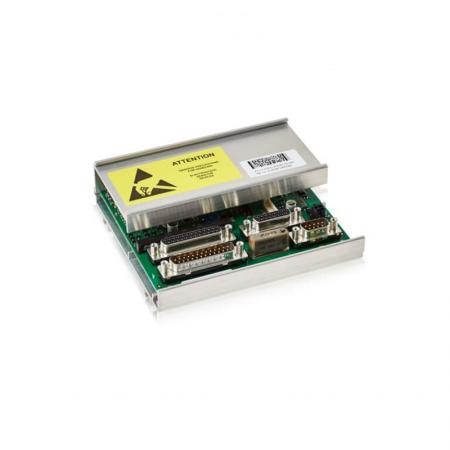
ABB 5SHX1060H0003 Reverse Conducting Integrated Gate

​Product Overview

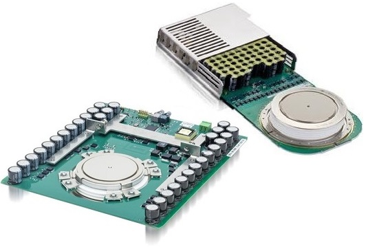
ABB 5SHX1060H0003 is a Reverse Conducting Integrated Gate Commutated Thyristor (RC-IGCT). It combines the high voltage withstand capability of thyristors and the gate controllability of transistors, occupying an important position in the field of high-power power electronics. This type of device is mainly used in industrial equipment that requires precise control of high current and high voltage, and can efficiently achieve the conversion and control of electrical energy.

Structure and Working Principle

Structural features: Its structure is similar to traditional gate turn off thyristors (GTOs), but has been optimized and improved. In 5SHX1060H0003, the gate turn off current is designed to be greater than the anode current. This unique design allows for the complete elimination of minority carriers injected from the lower PN junction, significantly accelerating the turn off time. In addition, compared to GTO, its unit size is smaller, the gate connection is more robust, and the inductance between the gate drive circuit and the drive circuit connection is greatly reduced. These structural advantages lay the foundation for its high-performance performance.

Working principle: In the conductive state, a suitable trigger signal is applied through the gate to make the thyristor conductive, allowing current to flow from the anode to the cathode. When it is necessary to turn off, a reverse signal is applied to the gate, and its special structure is used to achieve fast turn off. The reverse conduction characteristic allows current to conduct in reverse under specific conditions, which simplifies the design and reduces the use of external components in some circuit topologies.

Technical parameters

Current parameters: capable of carrying large currents, its rated on state average current and peak current parameters ensure stable transmission and control of large currents in high-power applications. For example, in high-power motor drive systems, it can meet the high current requirements during motor start-up and operation.

Switching frequency: The typical switching frequency is within a certain range (such as around 500 Hz), but unlike GTO, its upper limit switching frequency is mainly limited by the heat loss during operation and the system’s heat dissipation capacity. In practical applications, when the system has good heat dissipation, its switching frequency can even reach a high level in a short period of time (such as a 40kHz pulse burst), which provides the possibility for some applications that require high switching speed.

Working temperature range: It has a wide working temperature range, such as from -40 ℃ to 150 ℃. This allows it to work normally under different environmental conditions, whether it is outdoor equipment in cold regions or industrial plants in high-temperature environments, it can operate stably.
Integrated Gate-Commutated Thyristors | Iconopower

Advantages

Efficient switch performance: Fast switch speed, especially turn off speed, can effectively reduce switch losses and improve the overall efficiency of the system. In application scenarios with frequent switching, such as high-frequency inverters, this efficient switching performance can significantly reduce energy waste.

Simplified circuit design: The reverse conducting structure reduces the use of external diodes and other components, making the circuit layout more compact and reducing circuit complexity and cost. For example, in some inverter designs, using 5SHX1060H0003 can reduce the area of the circuit board and lower the complexity of connections between components.

High reliability: Optimized structure and advanced manufacturing technology enable it to have high reliability and operate stably for a long time under harsh working conditions. This is of great significance for some applications that require extremely high reliability of equipment, such as key node equipment in power systems, which can reduce equipment failures and maintenance costs.

Application Fields

Industrial frequency conversion speed regulation: used in the main circuit of the frequency converter in industrial motor drive systems. By precisely controlling the power supply frequency and voltage of the motor, efficient speed regulation of the motor can be achieved, meeting the speed regulation needs in different industrial production processes. It is widely used in the drive of equipment such as fans, water pumps, compressors, etc., achieving the goals of energy conservation and precise control.

Power system: In high-voltage direct current transmission (HVDC) systems, it can be used in the converter of the converter station to achieve efficient conversion between alternating current and direct current. Meanwhile, in the reactive power compensation device of the power system, the reactive power can also be adjusted by controlling its conduction and shutdown to maintain the stability of the grid voltage.

Rail transit: plays an important role in the traction system of subway, high-speed rail and other rail transit systems. By controlling the driving current and voltage of the motor, the smooth start, acceleration, deceleration, and braking of the train are achieved, ensuring the efficient operation and safety of rail transit.

New energy power generation: used in the inverter part of wind power and solar photovoltaic power generation systems. Convert unstable direct current into alternating current that meets the requirements of the power grid, achieving grid connected power generation of new energy. For example, in centralized inverters for large wind farms, 5SHX1060H0003 can achieve efficient conversion and control of large-scale electrical energy.

ABB 5SHX1060H0003 3BHB020538R0001 IGCT模块 - 雄霸工业

ABB Advant Controller 31 Series 07 KT 97/96/95 Basic

Product Overview

location:

The basic unit of the ABB Advant Controller 31 series intelligent distributed automation system supports independent operation or serves as a bus master/slave, suitable for industrial automation control scenarios.

Model classification:

07 KT 97: Standard model, supports up to 480 kB of user programs and 256 kB of user data, equipped with CS31 system bus, optional communication modules such as ARCNET, PROFIBUS-DP, Ethernet, etc.

07 KT 96/95: Simplified performance model with fewer digital input/output channels, no analog input or only supports basic functions (such as 07 KT 95 with only 4 analog inputs).

Hardware specifications and functions

1. Core hardware parameters

Parameters: 07 KT 97 07 KT 96 07 KT 95

Digital input: 24 channels (3 groups, 8 channels per group, electrically isolated) 24 channels (3 groups, 8 channels per group, electrically isolated) 12 channels (2 groups, 6 channels per group, electrically isolated)

Digital output: 16 transistor outputs (2 groups, 8 channels per group, electrically isolated) 16 transistor outputs (2 groups, 8 channels per group, electrically isolated) 8 transistor outputs (1 group, electrically isolated)

Analog input: 8 channels (configurable as voltage, current, Pt100, etc., supporting differential input) -4 channels (only supporting voltage and current input)

Analog output: 4 channels (configurable as voltage and current output) -2 channels (current output)

Communication interfaces: COM1/COM2 (RS-232), CS31 system bus, optional ARCNET/PROFIBUS-DP/Ethernet COM1/COM2 (RS-232), CS31 system bus COM1/COM2 (RS-232), CS31 system bus

Storage and Expansion: SmartMedia Card (up to 8 MB), Supports CS31 Bus Expansion SmartMedia Card (up to 2 MB) SmartMedia: Card (up to 2 MB)

Power supply: 24 V DC 24 V DC 24 V DC

2. Key functions

Input/output flexibility:

Analog input supports multiple signal types (0-10 V, 4-20 mA, Pt100, etc.), and some models can be configured as digital inputs.

The digital output has short-circuit/overload protection and supports demagnetization of inductive loads.

Communication ability:

Standard RS-232 interface (COM1/COM2), supporting Modbus protocol for programming and data transmission.

Optional communication modules such as ARCNET, PROFIBUS-DP, CANopen, Ethernet, etc. are available to adapt to different industrial network architectures.

Data storage and backup:

Built in Flash EPROM to store programs and data, supporting SmartMedia card backup of user programs, firmware upgrades, and data storage.

Lithium battery (07 LE 90) backup RAM data and real-time clock, with a lifespan of approximately 5 years (25 ° C).

High speed counter:

Integrated high-speed hardware counter, supporting 7 working modes, with a maximum counting frequency of 50 kHz, used for position or speed monitoring.

Communication Protocol and Interface

1. CS31 system bus

Function: Used to expand distributed I/O modules, supporting up to 31 remote modules, with an expansion capability of 992 digital inputs/outputs and 224 analog inputs/outputs.

Connection: Connected through twisted pair cables, with a 120 Ω terminal resistor added at the end of the bus, supporting ring or linear topologies.

2. Optional communication module

ARCNET:

Based on the token passing protocol, it supports coaxial cables (RG-62/U) with a transmission rate of 2.5 Mbit/s, a maximum length of 300 meters per segment, and a maximum of 255 nodes.

PROFIBUS-DP:

Compliant with EN 50170 standard, supports RS-485, transmission rates ranging from 9.6 kbit/s to 12 Mbit/s, with a maximum of 126 nodes (via repeaters).

Ethernet:

Supports TCP/IP, UDP/IP, Modbus TCP, 10/100 BASE-TX interface, connected via RJ45, supports SNMP network management.

CANopen:

Based on CAN bus, supporting a transmission rate of 1 Mbit/s and up to 127 slave stations, suitable for distributed motion control scenarios.

​Installation and maintenance

Installation method:

Supports DIN rail installation or wall screw fixation, with dimensions of 240 × 140 × 85 mm and a weight of 1.6 kg.

A SmartMedia card slot space needs to be reserved (with a 30mm clearance on the right side).

Maintenance points:

Regularly check the status of the lithium battery (replace it when the red LED is on).

The communication module needs to be matched with bus terminal resistors to ensure EMC compatibility.

Monitor I/O status, fault codes, and real-time clock through HMI or programming software (such as 907 AC 1131).

Application scenarios

Industrial automation: logic control and data acquisition in production line control, mechanical processing, and process automation.

Distributed system: As a master or slave, it connects to industrial networks such as ARCNET and PROFIBUS to achieve device linkage.

Motion control: Utilizing high-speed counters and CANopen modules to support servo motor or encoder feedback.

Building automation: Integrate into SCADA system through Modbus or Ethernet interface to monitor HVAC, power and other equipment.

Model comparison and ordering information

07 KT 97 R200 standard type, without built-in communication module GJR5 2530 00 R0200

07 KT 97 R0220 with built-in PROFIBUS-DP module GJR5 2530 00 R0220

07 KT 97 R0260 with built-in ARCNET module GJR5 2530 00 R0260

07 KT 96 R0100 No analog input, 16 digital outputs GJR5 2529 00 R0100

07 KT 95 R0100 4-channel analog input, 8-channel digital output GJR5 2528 00 R0100

Accessories: System cable (07 SK 90/91/92), lithium battery (07 LE 90), SmartMedia card (07 MC 90).

Summarize

The ABB 07 KT 97/96/95 series basic unit is a highly flexible industrial controller, suitable for small and medium-sized automation systems through rich I/O configuration and communication expansion capabilities. Its modular design and multi protocol support enable it to perform well in distributed control, motion monitoring, and remote communication scenarios. When combined with ABB programming software and bus systems, it can achieve efficient industrial automation solutions.

C310Wall-/Pipe-mount Universal Process Controller

Product overview

location:

A highly versatile single loop controller with an IP66/NEMA 4X wall/pipe mounting enclosure, suitable for process control in harsh environments, without the need for expensive instrument panels, and can be directly installed near equipment.

Core functions:

Support PID control, Ramp/Soak program settings, multiple input/output types, with Modbus communication function, suitable for temperature, pressure, flow and other parameter control in industrial processes.

Key functional characteristics

1. Input/output capability

Universal input (3-channel):

Supports signals such as thermocouple (THC), thermistor (RTD), millivolt, current (4-20mA), voltage, etc., with an accuracy of ± 0.1%, and built-in cold junction compensation (CJC).

Input impedance: millivolts/thermocouple>10M Ω, voltage 500k Ω, current 10 Ω.

Control output:

Analog output: 0-20mA, load ≤ 750 Ω, isolated 1kV AC.

Logic output: 12V DC (driving solid-state relay SSR), load ≤ 400 Ω.

Relay output: 3 SPDT relays (5A/120-240V AC), configurable for timed proportional control, valve drive, or alarm.

Auxiliary output:

Retransmission output (0-20mA), configurable as process variable, setpoint, or position feedback.

Two digital inputs (such as remote set point, valve position feedback).

2. Control and Programming

PID control: Supports P, PI, and PID modes, with built-in Autotune function.

Slope/Insulation Procedure:

9 programs, each with 30 segments, supporting segment event control of relay actions, suitable for scenarios such as heat treatment and temperature curve control.

Hot/Cold Control Strategy: Implement dual output control for heating/cooling through analog output and relay combination.

3. Communication and Integration

Interface: RS485 Modbus RTU protocol, 4-wire system, baud rate 1.2-9.6kbps, supports SCADA and PLC system integration.

Function: It can remotely transmit process data, set parameters, read status, and is compatible with Modbus function codes (such as reading registers and writing set values).

4. Environment and Protection

Protection level: IP66/NEMA 4X, dustproof and waterproof, suitable for humid, dusty or corrosive environments.

Working temperature: -10 ° C to 55 ° C (14 ° F to 131 ° F), humidity 0-95% (non condensing).

Electromagnetic compatibility (EMC): compliant with IEC 61326 standard, resistant to radio frequency interference (RF) and voltage spikes (>2kV).

Specification parameters

Display: 2 x 6-digit red LED, 0.56-inch (14mm) seven segment display, display range -9999 to+9999.

Power supply: 115V or 230V AC (± 15%), 50/60Hz, power consumption<10VA, supports brief power outage protection (<60ms without impact).

Accuracy: Measurement error ± 0.1% reading or ± 5 μ V, linearization error ± 0.1 ° C (typical value).

Size and weight: 160 x 250 x 107mm (height x width x depth), weight 2kg, supports wall or pipe installation (accessory 4600/0138).

Certification: CE, CSA/FM Class 1 Div.2 (hazardous area certification).

Application scenarios

Industrial process control: temperature and pressure closed-loop control in chemical, pharmaceutical, and food processing.

Heating, Ventilation, and Air Conditioning (HVAC): Valve control, heating/cooling system regulation.

Machinery and equipment: Slope heating/insulation control for heat treatment furnaces and reaction vessels.

Distributed system: Integrated into SCADA system through Modbus to achieve remote monitoring and data acquisition.

Ordering Information

Model example:

C310/01 1 3/STD

01: RS485 Modbus Communication

1: 115V AC power supply (with polarized plug)

3: CSA/FM Class 1 Div.2 certification

STD: Factory Standard Configuration

Optional accessories: Pipe Installation Kit (4600/0138), Custom Programming Service (CUS).

Summarize

ABB C310 is a compact, high protection process controller that is suitable for industrial scenarios that require on-site installation and remote monitoring, thanks to its universal input-output, flexible PID control, and Modbus communication capabilities. Its slope/insulation function and multi relay configuration make it perform well in complex process control, while the IP66 protection level ensures reliability in harsh environments.

ABB REF610 feeder protection relay Fault recording

 Fault recording function

1. Fault record types and storage

Event record:

Up to 100 events can be recorded, including protection phase start/trip, digital input status changes, communication anomalies, etc. Each event contains a timestamp (accurate to milliseconds), event code, and relevant parameter values (such as fault current, phase imbalance, etc.).

Events are sorted by priority, with the highest priority being internal relay failure (IRF), followed by trip events, and finally start/alarm events.

Fault Record (FR):

Record detailed data of the last 5 faults, including three-phase current, ground current, thermal level, triggering stage, and duration at the time of the fault, and support reading through parameters V1-V24.

The data is stored in non-volatile memory (EEPROM), retained after power failure, and can be cleared through Master Reset.

2. Trigger and Query

Trigger condition:

Internal protection stage actions (such as overcurrent, ground fault), external digital input triggering, manual triggering (via SPA parameter M1).

Support setting trigger thresholds (such as current exceeding the set value) and edge triggers (rising/falling edge).

Query method:

Read event codes and data through HMI menu or serial communication (SPA/Modbus, etc.).

Support filtering by time sequence or event type, with fault codes corresponding to specific fault types (such as IRF code 4 indicating output relay PO1 fault).

3. Fault diagnosis and alarm

Internal Relay Failure (IRF):

When a permanent fault is detected (such as program memory error, hardware failure), the green LED flashes, the LCD displays a fault code (such as 30 indicating program memory failure), and all outputs are locked.

Warning:

Non fatal faults (such as low battery level, abnormal communication module), yellow LED activation, LCD display warning code (such as 1 indicating low battery), relay continues to operate but some functions may be limited.

External instructions:

Send fault warnings through signal output (SO2) or communication interface, supporting remote monitoring.

Communication function

1. Communication interface and protocol

Front end interface:

Infrared interface: supports wireless or cable connection (IrDA) ®  Standard), only used for SPA bus protocol, with a fixed baud rate of 9.6 kbps, used for local parameter configuration and data reading.

Backend interface (optional module):

Fiber optic (plastic/glass): Supports SPA bus, IEC 60870-5-103 protocol, anti electromagnetic interference, suitable for long-distance communication.

RS-485: Supports Modbus RTU/ASCII, DNP 3.0 protocols, can connect up to 32 nodes, and has a bus length of up to 1200 meters.

DNP 3.0 module: dedicated to DNP 3.0 protocol, supports 2-wire or 4-wire half duplex communication, suitable for smart grid systems.

2. Supported communication protocols

SPA bus:

ABB specific protocol, used for local parameter settings and firmware upgrades, supports password protection (SPA password V160 is required).

IEC 60870-5-103:

Compliant with power system communication standards, used for transmitting measurement values, status data, and event records, supporting cyclic queries (GI) and emergency reporting.

Modbus RTU/ASCII:

Industrial universal protocol, supporting function codes 01-04, 05-06, 15-16, etc., readable and writable registers (such as HR/IR) and coils (DI/CO).

DNP 3.0:

Supports event grading (Class 1-3) and non sold reporting, suitable for remote terminal unit (RTU) communication, configurable scaling factor and dead zone.

3. Data transmission and configuration

Parameter Mapping:

Analog quantities (such as current, heat level) and digital quantities (such as output status, DI signal) are mapped to Modbus registers (such as HR404 corresponding to L1 phase current).

User defined registers (UDRs) can be associated with any register, facilitating custom data mapping.

Communication parameters:

Baud rate: 9.6/4.8 kbps (SPA/IEC 103), configurable to 2.4/1.2/0.3 kbps (Modbus).

Parity check: none/odd/even, data bits: 7/8 bits, stop bits: 1/2 bits.

Network topology:

Supports Loop or Star topologies, fiber optic modules require terminal resistors (120 Ω) and bias resistors to be configured.

4. Time synchronization and remote control

Time synchronization:

Synchronize real-time clock with an accuracy of ± 2.5 ms (second pulse) through digital input (minute pulse/second pulse) or communication protocol (such as DNP 3.0).

Remote control:

Remote modification of protection parameters, triggering tests, resetting counters, or clearing event records through Modbus or SPA protocols.

Support remote tripping and reclosing control through communication modules.

Collaborative application of fault recording and communication functions

Remote fault diagnosis:

Fault events are uploaded in real-time to the monitoring system through the communication interface, and support reading fault codes and data (such as V168 warning codes and V169 IRF codes) from registers through Modbus function codes 03/04.

Disturbance Recorder:

When a fault is triggered, it automatically records the analog signals (such as current waveforms) and digital signals before and after the fault, and supports downloading them to a PC for analysis through a communication interface (COMTRADE format).

Firmware Upgrade and Configuration Management:

Upgrade relay firmware remotely through communication interface, or batch configure multiple device parameters through SPA bus to improve maintenance efficiency.

Key parameters and limitations

Fault record capacity: 100 events+5 detailed fault records (FR)

Communication baud rate range: SPA/Modbus: 0.3-9.6 kbps; IEC 103: 9.6 kbps; DNP 3.0: configurable up to 38.4 kbps

Maximum number of nodes: RS-485/DNP 3.0: 32; Fiber optic ring network: no explicit restrictions (depending on topology)

Data transmission delay: Typical response time of 20-100 ms (Modbus), disturbance record download time depends on the amount of data

ABB REF610 Feeder Protection Relay

product overview

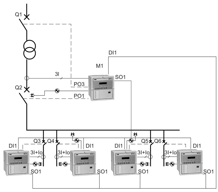
Purpose: REF610 is a multifunctional feeder protection relay mainly used for incoming and outgoing line protection in medium voltage distribution substations. It can also be used as backup protection for motors, transformers, and generators, and is suitable for industrial and utility applications.

Core functions: It has multiple protection functions such as overcurrent protection, ground fault protection, thermal protection, phase failure protection, circuit breaker failure protection, arc protection, automatic reclosing, etc. It supports real-time data monitoring, fault recording, and communication functions.

Technical Characteristics

Protection function:

Overcurrent protection: includes low setting stage (I>), high setting stage (I>>), and instantaneous stage (I>>>), supports definite time and inverse time (IDMT) characteristics, and can adapt to different fault scenarios.

Ground fault protection: Non directional, divided into low setting value (I0>) and high setting value (I0>>) stages, supporting IDMT characteristics.

Thermal protection: Simulate cable thermal overload and achieve overload warning and tripping by calculating the thermal capacity (θ>).

Arc protection: Detecting arcs through optional light sensors, supporting single relay or multi relay linkage, and quickly tripping.

Automatic Recloser (AR): Supports 1-3 reclosures and can be configured with different dead time and reclosing sequences.

Measurement and Communication:

It can measure parameters such as three-phase current, grounding current, and phase imbalance with an accuracy of ± 3%.

Supports multiple communication protocols, including SPA bus IEC 60870-5-103、Modbus RTU/ASCII、DNP 3.0, Supports fiber optic or RS-485 interfaces.

Hardware and Interface:

Input/Output: 4 current inputs (supporting 1A/5A rated current), 2-5 digital inputs, 3 power outputs (PO), and 2-5 signal outputs (SO).

Communication module: Optional plastic fiber optic, glass fiber optic, RS-485 and other modules, supporting arc protection input.

Human Machine Interface (HMI): Equipped with an LCD display and navigation buttons, supporting multilingual password protection.

Specification parameters

rated voltage

Auxiliary voltage: AC 100-240V or DC 24-250V (different models are optional)

Rated current

Phase current: 1A or 5A; Grounding current: 0.2A/1A/5A (optional)

Working temperature: -10 ° C to+55 ° C (long-term), short-term can reach -40 ° C to+70 ° C

Protection level: Front IP54, Rear IP20

Communication speed

SPA/Modbus:9.6/4.8 kbps; IEC 103:9.6 kbps

Dimensions and Weight: Width 177mm, Height 177mm, Depth 149.3mm; Weight Approximately 3.5kg

Application scenarios

Power system: feeder protection for medium voltage distribution substations, including incoming, outgoing, and busbar protection.

Industrial automation: Overload and fault protection for motors, transformers, and generators, suitable for fields such as chemical, steel, and manufacturing.

Arc protection scenario: Arc detection and rapid tripping in air insulated metal armored switchgear to ensure the safety of personnel and equipment.

Smart grid: supports remote monitoring and communication, and can be integrated into substation automation systems (SCADA).

Installation and maintenance

Installation method: Supports semi embedded, wall mounted, or 19 inch rack installation, ensuring good ventilation and electromagnetic compatibility.

Maintenance points:

Regularly check the input/output wiring and communication module status.

Perform preventive maintenance (such as battery replacement and functional testing) every 5 years.

Configure parameters and read fault records through HMI or dedicated software (Relay Setting Tool).

Ordering Information

Model example: REF610C55HCNP01 (including RS-485 communication module, 5A phase current input, English interface).

Optional accessories: fiber optic communication module, arc light sensor, installation kit, front communication cable, etc.

Safety and Compliance

Certification: Compliant with IEC 60255, EN 55011, EMC 2004/108/EC and other standards, passed tests such as dielectric, surge, EMC, etc.

Safety Warning: Internal high voltage danger, requires installation by professional electricians to ensure reliable grounding and avoid static electricity damage to components.

ABB 3HAC022286-001 Serial measurement unit DSQC 633

Product Overview

ABB 3HAC022286-001 Serial Measurement Unit DSQC 633 is a high-precision measurement device designed specifically for the industrial automation field, especially for robot control systems. It achieves real-time monitoring and feedback of robot motion status through precise collection and processing of sensor data, effectively improving the accuracy, stability, and safety of robot operation. It is widely used in automated production lines and complex industrial operation scenarios that require high precision.

Core functions

Multi type data collection: can connect multiple sensors, such as encoders, tilt sensors, etc., to collect data on robot joint angles, positions, velocities, etc., providing comprehensive information for robot motion control.

High precision data processing: Equipped with advanced algorithms, the collected data is filtered, calibrated, and analyzed to ensure the accuracy and reliability of the output data, meeting the requirements of high-precision operations.

Real time data transmission: The measurement data is transmitted to the robot controller in a stable and fast manner through a serial communication interface, achieving real-time data interaction and ensuring the dynamic response capability of the robot.

Fault diagnosis and warning: It has self diagnostic function, monitors its own working status in real time, and can issue warning signals in a timely manner when abnormalities occur, which facilitates maintenance personnel to quickly locate and solve problems, reducing downtime.

Working principle

DSQC 633 is connected to various sensors through a serial communication interface. The sensors convert the physical motion parameters of the robot (such as angle and displacement) into electrical signals and transmit them to the measurement unit. The signal conditioning circuit inside the measurement unit amplifies, filters, and preprocesses the original signal to eliminate interference and noise; Next, the analog-to-digital converter converts the analog signal into a digital signal, which is then analyzed and calculated by a microprocessor using specific algorithms to obtain accurate measurement results. Finally, the measurement unit transmits the processed data in real-time to the robot controller according to the established communication protocol. The controller adjusts the robot’s motion trajectory and posture based on this data to achieve precise control.

Key advantages

High precision measurement: With extremely small measurement errors, it can meet the precision requirements of applications such as precision manufacturing, ensuring the quality of product processing.

High reliability: Using high-quality components and mature designs, it has excellent anti-interference ability, adapts to complex industrial environments, and reduces failure rates.

Flexible adaptation: Supports multiple sensors and communication protocols, compatible with different models of robots and control systems, facilitating system integration and upgrading.

Easy to maintain: Modular design and intuitive fault diagnosis function enable maintenance personnel to quickly identify and replace faulty components, reducing maintenance difficulty and costs.

Precautions

Installation environment: It should be installed in a dry, well ventilated and non corrosive gas environment, avoiding high temperature, high humidity and strong electromagnetic interference, to prevent affecting measurement accuracy and equipment life.

Wiring specifications: Strictly follow the instructions for wiring to ensure a secure connection and avoid equipment damage or abnormal data transmission caused by wiring errors.

Regular calibration: To ensure measurement accuracy, the measuring unit needs to be calibrated regularly, and the calibration cycle can be determined according to the actual frequency of use and environment.

Power off operation: When installing, disassembling, or maintaining equipment, be sure to cut off the power supply to prevent electric shock and equipment damage.

Similar model supplement

DSQC 634: Similar in functionality to DSQC 633, but with upgraded communication interface types and data processing capabilities, suitable for large automated production lines with higher requirements for data transmission speed and compatibility.

DSQC 632: focuses on basic measurement functions, with relatively low prices, suitable for small and medium-sized enterprises or simple automation application scenarios that are cost sensitive and do not require extremely high measurement accuracy.

DSQC633 3HAC022286-001 Serial measurement unit ABB | saulcontrol

ABB DSQC332A Digital I/O Module

Product Overview

ABB DSQC332A is an advanced digital input/output module designed specifically for industrial automation systems, playing a critical role in signal interaction and control in various automation scenarios. Its design purpose is to provide reliable digital signal input and output functions for industrial equipment, ensuring efficient and accurate data transmission and instruction execution between devices, thereby improving the operational performance and stability of the entire automation system. Whether in complex production lines or process control systems that require strict control accuracy, DSQC332A can provide strong support for the smooth implementation of automated operations based on its own characteristics.

Brand background

ABB, as a global giant in the fields of electrical and automation technology, has a glorious history of over 130 years. In the long process of development, ABB has continuously invested in research and development resources, constantly innovated, and accumulated a profound technical foundation. Our business scope covers over 100 countries worldwide, serving numerous core areas such as energy, industry, transportation, and infrastructure. By relentlessly pursuing quality and steadfastly adhering to innovation, ABB has established an outstanding brand image, and its products and services are highly trusted by customers worldwide. The DSQC332A digital input/output module is a typical representative of ABB’s advanced technology and reliable quality, demonstrating the brand’s leading position and professional level in the field of industrial automation.

Specification parameters

product type:Industrial I/O modules

brand:ABB

model:DSQC332A

Channel:8 of them

Output channel:8 of them

working voltage :24V DC

Rated current value:0.5A per channel

Working temperature range:-25 ° C to+60 ° C

Storage Temperature Range:-40 ° C to+75 ° C

humidity:≤75%

communication protocol:Profibus DP

weight:0.25kg

External dimensions:Length 120mm x Width 90mm x Height 50mm

protection grade:IP20

authentication:Having international certifications such as UL, CE, CSA, etc

Core functions

Digital signal input and output: The module is equipped with 8 input channels and 8 output channels, which can accurately collect digital signals from external sensors, such as equipment operation status signals, position detection signals, etc., and output digital instructions issued by the control system to corresponding actuators, such as motor drivers, solenoid valves, etc., to achieve effective linkage and automation control between devices.

Data transmission and communication: Supports Profibus DP communication protocol, which is known for its high-speed and reliable data transmission characteristics, ensuring that DSQC332A can seamlessly interface and efficiently interact with other industrial automation equipment, such as programmable logic controllers (PLCs), industrial computers, etc., to ensure the overall coordinated operation of the system.

Working principle

In the input stage, when the external sensor generates a digital signal change, the input channel of DSQC332A will sense this change and convert it into an identifiable electrical signal inside the module. After undergoing internal circuit conditioning, amplification, and logical judgment, these signals are transmitted to the control system through the Profibus DP communication interface according to a specific communication protocol. In terms of output, the instructions issued by the control system are transmitted to DSQC332A through the Profibus DP communication link. The module parses the received instructions and then drives the circuit of the output channel to output corresponding digital signals to control the action of external actuators, thus completing the signal input and output loop in the entire automation control process.

Key advantages

High reliability: The module adopts high-quality electronic components and advanced manufacturing processes, fully considering the strictness of the industrial environment in its design. It has excellent anti-interference ability and can effectively resist adverse factors such as electromagnetic interference and power fluctuations, ensuring stable and reliable operation in complex industrial scenarios and greatly reducing the risk of system shutdown caused by module failures.

Strong compatibility: With support for the Profibus DP communication protocol, it can be easily integrated into various mainstream industrial automation system architectures. Whether it is upgrading existing systems or building new automation projects, it can achieve good compatibility with different brands and types of equipment, providing great convenience for system integrators and users.

Easy installation: The compact exterior design takes up less space, making it easy to install within limited control cabinet space. At the same time, standardized interfaces and wiring methods simplify the installation process, reduce installation difficulty, effectively shorten project implementation cycles, and improve engineering construction efficiency.

Stable performance: With a wide operating temperature range and humidity tolerance, DSQC332A can adapt to various harsh industrial environments, from cold northern factories to hot and humid southern workshops, maintaining stable performance and ensuring the continuity and consistency of automated production.

Precautions

Installation environment: It is necessary to install the module in a dry, well ventilated place, away from high temperature, high humidity, and strong electromagnetic radiation areas. High temperature environment may accelerate component aging, high humidity can easily cause short circuit faults, and strong electromagnetic interference may lead to signal transmission errors, affecting the normal operation of the module.

Wiring operation: Strictly follow the wiring diagram in the product manual to ensure that the wiring is firm and correct, and to avoid false or incorrect connections. Wiring errors may not only cause the module to malfunction, but also damage the module or other equipment, leading to safety accidents.

Power adaptation: Provide stable and compliant 24V DC power supply for the module to prevent voltage fluctuations beyond the allowable range. Unstable power supply may cause abnormal module operation and even damage internal circuits, so it is recommended to equip with high-quality power stabilizer devices.

Regular maintenance: Regularly inspect and maintain the module, including visual inspection (to check for physical damage, corrosion, etc.), functional testing (to verify whether the input and output signals are normal), etc. Timely clean the dust on the surface of the module, maintain good heat dissipation, ensure that the module is in the best working condition for a long time, and extend its service life.

Similar model supplement

DSQC332: As the basic version of DSQC332A, it is similar to DSQC332A in core functions and application scenarios, but DSQC332A has been optimized and upgraded in certain performance indicators such as anti-interference ability and communication speed. DSQC332 may be more suitable for small automation projects that are cost sensitive and have relatively low performance requirements.

DSQC652: Also a digital I/O module under ABB, DSQC652 has more input and output channels (usually 16 inputs and 16 outputs), suitable for complex automation systems that require processing large amounts of digital signals. Compared with DSQC332A, it has significant advantages in terms of channel quantity and processing capability, but may be relatively large in terms of volume and power consumption. Users need to choose based on factors such as the number of signal points required for the actual project, system space, and power consumption limitations.

ABB DSQC 328 3HAB 7229-1 Digital I/O Module

ABB HIEE205010R0003 UNS 3020A-Z, V3 Ground Fault Relay

Product basic information

Product Code: HIEE205010R0003.

Product Name: UNS 3020A-Z, V3 Grounding Fault Relay.

Country of Origin: Switzerland (CH).

Customs commodity code: 85364910.

Minimum order quantity: 1 piece.

Order multiplier: 1 piece.

Part type: brand new.

Inventory warehouse: Baden, Switzerland.

Product specifications and parameters

Dimensions: Net length/depth 485mm, net height 135mm, net width 230mm.

Weight: The net weight of the product is 5.17kg, and the gross weight and packaging gross weight are both 0kg.

Other attributes: Not classified as WEEE (Waste Electrical and Electronic Equipment), non customized product (Made To Order: No), supports regular ordering (Quote Only: No), sales unit is “piece”.

Product Overview

ABB HIEE205010R0003 UNS 3020A-Z, V3 Ground Fault Relay is a high-performance equipment designed specifically for industrial applications, playing a critical role in ensuring the safe operation of electrical systems. Its design aims to accurately detect grounding faults in the system, avoid safety accidents and equipment damage caused by leakage, and build a solid safety defense line for the stable development of various industrial production activities.

​Core functions

Grounding fault detection: With a highly sensitive detection mechanism, it can quickly and accurately identify grounding faults in electrical systems, even extremely small leakage currents can be detected in a timely manner, effectively avoiding the expansion of faults.

Fault alarm: Once a grounding fault is detected, the relay will immediately trigger an alarm signal, notify the operator in a timely manner through indicator light flashing, electrical signal output, etc., so as to take prompt response measures.

Circuit protection: Upon detecting a fault, quickly cut off the faulty circuit to prevent excessive fault current from causing damage to equipment and personnel, and protect the overall safety of the electrical system.

Working principle

The grounding fault relay mainly operates based on the principle of residual current detection. In normal operation, the vector sum of the currents in each phase of the electrical system is zero. When a grounding fault occurs in the system, residual current will be generated, that is, the sum of the current vectors of each phase is no longer zero. The current transformer inside HIEE205010R0003 will detect this residual current and convert it into an electrical signal to be transmitted to the core control unit of the relay. The control unit analyzes and processes the received signal. When the residual current exceeds the preset threshold, the control unit will issue instructions to drive the contact of the relay to act, thereby achieving the functions of alarm and cutting off the fault circuit.

Key advantages

High sensitivity and reliability: able to accurately detect small grounding faults, operate stably and reliably, with very few false alarms or missed alarms, providing a solid guarantee for electrical system safety.

Wide working range: It can work normally within a wide range of voltage, current, and temperature, with strong adaptability, and can meet the complex application requirements of different industrial environments.

Easy to install and integrate: The compact design makes the installation process simple and can seamlessly integrate with various existing electrical control systems without causing too many changes to the original system architecture.

Long service life: Made of high-quality materials and advanced manufacturing processes, it has excellent durability and can maintain stable performance during long-term use, reducing maintenance costs and equipment replacement frequency.

Precautions

Installation environment: It should be installed in a dry, well ventilated, and non corrosive gas environment, avoiding high temperature, high humidity, and strong electromagnetic interference to ensure the normal operation of the relay.

Wiring specifications: Strictly follow the wiring diagram in the product manual to ensure secure and correct wiring, and prevent relay misoperation or damage caused by wiring errors.

Regular maintenance: Regularly inspect and maintain the relay, including cleaning the housing, checking the contact status, testing performance, etc., promptly identify potential problems and solve them to ensure its long-term stable operation.

Parameter setting: According to the actual requirements of the electrical system, set the protection sensitivity and other parameters of the relay reasonably to avoid improper parameter settings affecting its protection effect.

Similar model supplement

UNS 3020A-Z, V1: It is an early version of HIEE205010R0003, which is similar in functionality to V3 version, but V3 has improved detection accuracy and response speed. In some application scenarios, V1 may have relatively lower costs and is suitable for situations where performance requirements are not particularly high.

UNS 2880B-P V2: focuses on grounding protection for specific electrical systems, and differs from HIEE205010R0003 in terms of rated current and voltage parameters. It is suitable for industrial equipment or small electrical systems with special requirements for current and voltage specifications.

ABB F360 X Residual current operated circuit-breakers (RCCB)

Product overview

Type: Residual Current Operated Circuit Breaker (RCCB), belonging to the STOTZ series, models include F 362 X (2-pole) and F 364 X (4-pole), rated currents of 80A and 100A, and rated residual current of 30mA.

Core functions:

Detect AC fault current, with surge resistance of 250A (8/20 μ s waveform) and 200A (0.5 μ s/100kHz circular wave).

Provide indirect contact (protection against electric shock), direct contact (additional protection), and electrical fire protection (when residual current ≤ 300mA).

Working principle: The residual current is detected by a balanced transformer with a permanent magnet release. When the current exceeds the rated value, the circuit is quickly cut off with a response time of ≤ 200ms (1.1 times the rated residual current).

Technical Parameter

Standard IEC 1008, EN 61008, BS 4293

2 poles and 4 poles

Rated voltage 230/400V (AC)

Frequency 50-60Hz

Rated short-circuit current 6000A (independent); When combined with upstream gL 100A fuses or S 700 E 100 circuit breakers, it can reach 10kA

Protection level IP20 (regular), IP40 when installed on the distribution board

Environmental temperature -25 ° C to+55 ° C

Connecting wires of 1.5-25mm ², multiple thin wires require connectors or cable lugs

Mechanical lifespan of at least 5000 switch cycles

Weight: F 362 X about 0.28kg, F 364 X about 0.43kg

Installation and operation

Installation requirements:

Operated by authorized personnel, installed with DIN rail (EN 50022, 35mm) snap fasteners, supporting any direction.

When connecting aluminum wires, it is necessary to clean the contact surface, apply grease, and re tighten the terminals after 6-8 weeks.

When a 4-pole circuit breaker is used as a 2-pole circuit breaker, terminals 5 and 7 (or 6 and 8) need to be connected. When there is no neutral wire in a three-phase circuit, terminals 4 and 8 need to be bridged.

Operational testing:

Press the test button every month, and the circuit breaker should trip immediately (the operating lever should jump from “I” to “0”).

It is necessary to regularly test the effectiveness of protection and verify that the grounding resistance meets the standard (such as 833 Ω corresponding to a maximum contact voltage of 25V at 30mA).

Maintenance precautions:

Clean with soapy water and a damp cloth. Do not use corrosive cleaning agents or solvents.

When there is a malfunction, check the insulation of the downstream circuit and do not disassemble it by yourself, otherwise the warranty will be lost.

Application scenarios

Residential and commercial buildings: As an additional protection for socket circuits and residual current protection for main circuits, it complies with mandatory safety regulations.

Industrial and energy sectors: suitable for scenarios with high requirements for electric shock and electrical fire protection, such as factory power distribution and renewable energy systems.

Special circuit: Can be combined with miniature circuit breakers (MCBs) for single-phase or three-phase distribution systems, supporting bus bar connections (such as SZ-PSB series bus modules).

Accessories and Selection

Busbar module: used for horizontal connection of multi pole circuit breakers, such as SZ-PSB 53 N (2-pole, 10mm ², 213mm long), SZ-PSB 61 N (4-pole, 10mm ², 213mm long).

Terminal cover and shield: Provides IP20/IP55 protection level, such as PCD series terminal cover and QES insulated housing.

Installation guide rail: DSW series modular guide rail, supporting 2-6 modules (17.5mm/module).

Safety and Compliance

Anti electric shock protection: Compliant with DIN VDE 0106 Part 100, protection is achieved through system grounding configurations such as TN-S, TN-C-S, TT, IT, etc.

Warranty and Responsibility: Provide warranty according to standard sales terms, and raise quality objections in writing within 8 days after arrival.

Technical update: Document parameters may change, and the latest version shall prevail. We do not assume responsibility for the old version.

Brand and Series Expansion

Brand Background: ABB STOTZ-KONTAKT is a subsidiary of ABB Group, specializing in electrical installation systems and providing modular solutions such as System Pro M and System Connect.

Series comparison: F 360 X belongs to AC type RCCB, suitable for sinusoidal AC fault current; Type A/B products (such as F 370/F 804) are compatible with pulsating DC and pure DC residual current.

F360 Residual Current Circuit Breaker 4 Phase 16-63A DIN Rail Type RCCB ...

ABB SK616001-A contact block

Product Overview

ABB SK616001-A contact block is an input-output module that plays an important role in the field of industrial control. It is mainly used as the main control circuit interface board module for system components. Its emergence has revolutionized traditional control modes and plays a key role in many industrial scenarios, especially in fields such as wind power generation and gas turbine components that require high reliability and precision control.

Brand background

ABB, as a globally renowned leader in the fields of power and automation technology, has a long history of over 130 years. Its business covers over 100 countries worldwide, providing leading solutions in various fields such as energy management and industrial automation. With its profound technology accumulation, continuous innovation investment and persistent pursuit of quality, ABB brand has won a high reputation worldwide, providing a solid brand guarantee for the reliability and progressiveness of SK616001- A contact block.

Specification parameters

Rated voltage: It can adapt to various common voltage levels, depending on different application scenarios and usage requirements. Common AC voltage levels include 220V, 380V, etc., which can flexibly meet the power supply needs of various industrial equipment.

Rated current: The main contact has different current levels to choose from, covering scenarios from small current loads to large current loads, such as 10A, 20A, 40A, etc., to meet the control needs of different power devices.

Alternative mechanical switch device: This product can effectively replace traditional mechanical switch devices (relay modules), using advanced electronic control technology to achieve faster and more accurate circuit on/off control, greatly improving the system’s response speed and control accuracy.

System monitoring and control: It can not only achieve basic circuit control functions, but also monitor the real-time operation status of the entire system. By communicating with other devices, the monitored data is fed back to the control system for timely adjustment of control strategies, ensuring stable and efficient operation of the system.

​Working principle

SK616001-A contact block works based on advanced electronic signal processing principles. When receiving control signals from the control system, its internal electronic components will recognize and process the signals. By controlling semiconductor devices in the circuit, such as transistors, thyristors, etc., the conduction and cutoff control of the main circuit can be achieved. At the same time, sensors and feedback circuits are used to monitor real-time parameters such as current and voltage in the circuit, and this information is fed back to the control system to achieve closed-loop control and ensure the stability and reliability of the system operation.

Key advantages

High reliability: By using high-quality electronic components and advanced manufacturing processes, and undergoing strict quality inspection processes, the product ensures stable operation in various harsh industrial environments, effectively reducing equipment failure rates and improving production efficiency.

Precise control: Compared with traditional mechanical switch devices, it can achieve more precise circuit control, higher control accuracy for current and voltage, and can meet the demanding requirements of industrial application scenarios for control accuracy.

Easy to integrate: The product design follows standardized interface specifications, making it easy to integrate with other industrial equipment and control systems. It can quickly integrate into existing industrial automation production lines, reducing the difficulty and cost of system integration.

Precautions

Installation environment: It should be installed in a dry and well ventilated environment, avoiding installation in places with high temperature, humidity, dust or corrosive gases to prevent damage to product performance.

Electrical connection: When making electrical connections, it is necessary to ensure that the wiring is firm and correct, and avoid situations such as virtual connections and short circuits. At the same time, it is necessary to strictly follow the electrical parameter requirements in the product manual for wiring to prevent overload operation.

Regular maintenance: To ensure long-term stable operation of the product, it is recommended to conduct regular maintenance checks, including cleaning the product surface, checking for loose electrical connections, and monitoring the product’s operating status. If any abnormal situation is found, it should be dealt with in a timely manner.

Similar model supplement

ABB SK616002-A: Similar in functionality to SK616001-A, but with differences in certain parameters. For example, SK616002-A may have a wider range of choices in terms of rated current or voltage levels, suitable for some industrial scenarios with more specific electrical parameter requirements.

ABB SK616003-A: This model has been optimized in terms of system monitoring function, with stronger data acquisition and analysis capabilities, which can provide more detailed and accurate operating data for control systems. It is suitable for complex industrial automation systems with high requirements for system operation status monitoring.

LOT OF 4 NEW ABB SK-616-001-B CONTACT BLOCKS SK616001B - SB Industrial ...

Search for products

Back to Top
Product has been added to your cart