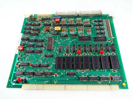
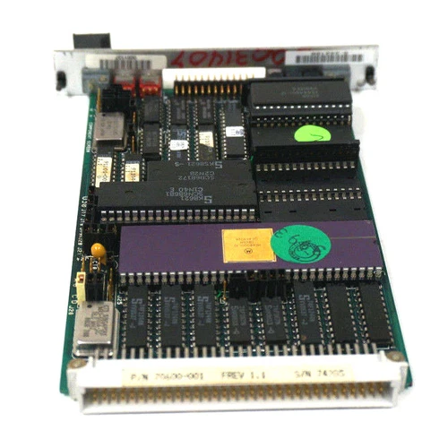
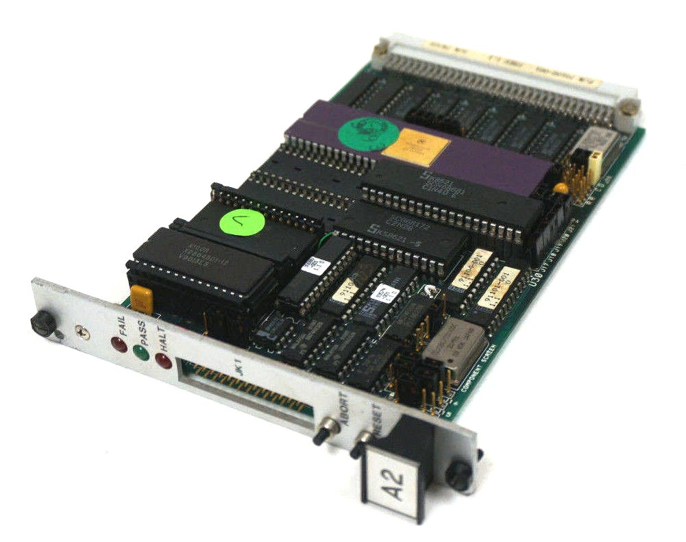
XYCOM AIO XVME-540 Analysis of I/O Module
Features
• 32 single-ended or 16 differential input channels
• Inputs are configurable as bipolar or unipolar
• 12-bit conversion
• Three ranges of programmable gain
• Jumper-selectable input/output voltage ranges
• Four input sampling modes
• Four output channels, each selectable for
voltage or current output
• Fully compatible with Analog Devices 3B
Signal conditioning
Applications
• Data acquisition
• Process control
• Pressure and temperature sensing
• Machine control
Overview
The XVME-540 Analog Input/Output Module is a powerful, VMEbus-compatible I/O module that
can perform 12-bit A/D and D/A conversions.
The XVME-540 contains 32 single-ended or 16 differential analog input channels.
The input channels can be programmed to operate in any one of four operating modes: random channel sampling, sequential channel sampling, single channel sampling, and sampling based on an
external trigger.
The XVME-540 has program mable gain available within one of three jumper selected ranges.
The XVME-540 also contains four analog output channels.
These output channels can be config ured as either voltage or current outputs.
Analog Outputs
Number of Channels:4
Accuracy
Resolution:12 bits
Overall error:±1/2 LSB
Differential linearity:±1 LSB
Voltage Output Characteristics
Ranges:0-5 V, 0-10 V, ±5 V, ±10 V
Output current:5 mA min. @ ±10 V
Settling time:50 µsec
Load resistance range:50-500 ohms
Offset T.C. 75 ppm/ºC
Gain T.C. 100 ppm/ºC
Current Loop Characteristics
Range:4-20 mA, non-isolated
Compliance voltage:10 V @ 20 mA
Loop supply voltage:+15 V to +30 V
Settling time:50 µsec
Load resistance range:50-500 ohms
Offset T.C. 75 ppm/ºC
Gain T.C. 100 ppm/ºC
Analog Inputs
Number of Channels
Single-ended:32
Differential:16
A/D Input Full Scale Voltage Ranges (G=1)
Unipolar:0-5 V, 0-10 V
Bipolar:±2.5 V, ±5 V & ±10 V
Programmable Gain
Range:1 1,2,5,or 10
Range:2 4, 8, 20, 50, or 100
Range:3 10, 20, 50, or 100
Maximum Input Voltage
Power on 44 V
Power off 30 V
Input Impedance
w/22 MΩ resistor 17 MΩ, min.
w/o 22 MΩ resistor 100 MΩ, min.
Bias Current:±100 nA, max.
Input Capacitance:225 pF, max.
Operating Common Mode Voltage:+13 V/-11 V
Common Mode Rejection:Ratio 60 db, min.
External Trigger to Sample:25 µsec
VMEbus Compliance
Complies with VMEbus Specification:IEEE 1014
A24/A16:D16/D08(EO) DTB Slave
Interrupter:(1)-I(7)(STAT), RORA
Interrupt Vector: D08(0)(DYN)
Interrupt Signals:SYSFAIL
Form Factor NEXP
Conforms to Xycom Automation Standard I/O Architecture
Product Overview
The XYCOM AIO XVME-540 I/O module is a high-performance industrial grade input/output module designed based on the VMEbus architecture, aimed at providing reliable and flexible signal interaction solutions for industrial automation control systems. As an important member of the XYCOM AIO (All In One) series, it highly integrates multiple I/O functions, can quickly collect and process various signals from industrial sites, and accurately output control instructions to actuators, playing a key role in industrial automation production lines, mechanical equipment control, energy management systems, and other fields.
Key advantages
High integration: integrating multiple I/O functions into one, reducing the number of modules in the system, lowering system complexity and cost, while improving system reliability and stability.
Flexibility and Scalability: Rich I/O channels and support for multiple communication protocols enable it to flexibly adapt to different industrial application scenarios and system requirements. Users can easily expand and upgrade the system according to their actual needs by increasing or decreasing the number of modules, adjusting module configurations, and other methods.
High reliability: using industrial grade components and strict manufacturing processes, it has excellent anti-interference ability and environmental adaptability. In harsh industrial environments such as high temperature, humidity, vibration, and strong electromagnetic interference, it can still operate stably for a long time, effectively reducing equipment failure rates and maintenance costs.
Easy to use and maintain: Provides standardized interfaces and communication protocols for easy connection and integration with other devices. Meanwhile, the user-friendly interface and comprehensive technical documentation enable engineers to quickly get started with programming, debugging, and maintenance work.
Precautions
Installation environment: During installation, a dry, well ventilated, and dust-free environment should be selected to avoid installing I/O modules in places with corrosive gases, large amounts of dust or water vapor, and to prevent electronic components from being corroded or damaged. At the same time, it is necessary to ensure that the installation location has good heat dissipation conditions to avoid affecting the performance and lifespan of the module due to high temperatures.
Wiring operation: When wiring the I/O module, it is necessary to ensure that the equipment is in a power-off state and strictly follow the wiring diagram and instructions to avoid module damage or system failure caused by wiring errors. For analog signals, shielded cables should be used for connection and grounding treatment should be done to reduce signal interference.
Static protection: When installing, disassembling, or maintaining I/O modules, operators must wear protective equipment such as anti-static wristbands to avoid damage to the precision electronic components on the module caused by human static electricity. During the operation, direct contact with electronic components and circuits should be avoided as much as possible.
Communication settings: When establishing communication connections and setting parameters, ensure that the communication protocol, baud rate, data format, and other parameters of the I/O module are consistent with those of other devices, otherwise communication failure may occur. During system operation, if communication parameters need to be changed, the relevant equipment should be stopped before setting the parameters.