32 channel design: includes 32 digital inputs (DI) and 32 digital outputs (DO), supports optoelectronic isolation, and can withstand electrical interference in industrial environments.
VME bus interface: compatible with the VME standard, suitable for industrial control systems that require high-speed data transmission (such as aerospace, semiconductor manufacturing).
Modular design: Supports hot plugging, easy maintenance and expansion, and can monitor channel status in real-time through LED indicator lights.
Technical parameters:
Working voltage: usually 24VDC (to be confirmed according to specific model).
Isolation characteristics: Optoelectronic isolation is used between the input/output channel and the VME bus, with an isolation voltage of ≥ 2500VAC.
Response time: Typical value ≤ 1ms, meeting real-time control requirements.
Verification and Risk Warning:
Product status: Suppliers are required to provide serial numbers or test reports to avoid purchasing non original or damaged equipment.
Compatibility verification: If used for old systems, the VME bus slot specifications (such as 6U size) and communication protocol (such as VME64x) need to be confirmed.
Compatibility and alternative solutions
System compatibility:
VME bus matching: It is necessary to ensure that the target system’s VME backplane supports 6U size modules and provides sufficient power supply (such as+5V,+12V).
Protocol support: Some VME systems require additional configuration of drivers or firmware. It is recommended to request technical documentation from the supplier in advance.
Recommended alternative solutions:
Pro Face alternative model: Pro Face does not directly provide a substitute product for 10330-00800. AGP 3xxx series industrial PCs with extended I/O modules (such as ADAM-4000 series) can be considered to achieve similar functions
Third party VME modules, such as Mercury Systems’ MVME 162-110 (32 channel DIO), are compatible with the VME64x protocol and support long-term spare parts supply.
Repair and maintenance recommendations
Fault diagnosis:
LED indicator light: Determine channel faults through the status lights on the module (such as a constant red light indicating a short circuit).
Self diagnostic function: Some VME systems support remote diagnosis and can read module error codes through software.
Compatibility testing:
Require suppliers to provide test reports or prototypes to verify the stability of the module in the target system. If software migration is involved, you can consult Pro Face for protocol conversion tools.
Central Processing Unit (CPU): executes instructions and supports standardized programming languages such as Ladder Diagram and Structured Text.
Input/Output Components (I/O):
Digital I/O: Processing switch signals (such as buttons, sensors).
Analog I/O: Processing continuous variables such as temperature and pressure.
Special I/O: Supports high-speed counters, communication modules, etc.
Power module: Provides stable voltage (such as 24VDC/120VAC), with built-in lithium battery to maintain power-off data.
Programming unit: Program development and simulation are carried out through PC software such as PLCLogix and RSLogix.
application area
Petroleum industry: Control the valves, pumps, and sensors of drilling equipment, and use HMI to achieve real-time monitoring.
Glass and cement industry: precise control of raw material ratios and production processes, combined with distributed control systems (DCS) to enhance quality control.
Manufacturing industry: Automated production line control in industries such as automobiles, food, and textiles.
development history
Origin: In 1969, Modicon introduced the first PLC (model 084) to replace relay logic systems.
Evolution: From single control to support Ethernet communication, HMI interface, and modular design, following the IEC 61131-3 programming standard.
Fundamentals of PLC Programming
programming language
Ladder diagram (LD): visually imitates relay circuits, suitable for logic control, using symbols such as normally open/normally closed contacts and coils.
Function Block Diagram (FBD): Representing logical functions (such as timers and counters) in graphical modules for system integration.
Structured Text (ST): A high-level language that is suitable for complex algorithms and supports variable and process control.
Basic instructions and scanning cycle
Scanning cycle: sequentially execute “input reading → program execution → communication processing → output update”, and the scanning time affects real-time performance.
Timer and counter:
TON (Power on Delay): The action is triggered when the timer reaches the preset value.
CTU/CTD (up/down counter): Counting based on input signal changes.
Program control instructions: JMP/LBL jump, SBR/RET subroutine call, optimize program structure.
Data Addressing and Storage
File Addressing System:
I/O File: Stores the physical input/output status (e.g. I: 3/12 represents terminal 12 of input module 3).
Data Files: including bit files (B3), integer files (N7), timer files (T4), etc., supporting addressing by word or bit.
Practical Technology and Optimization
SCADA System Fundamentals
Function: Data collection, network communication, real-time monitoring and control, presenting production status through HMI interface.
Components: Composed of PLC/RTU, sensors, communication networks (such as LAN/WAN), and SCADA software, used for industrial automation management.
Scan time optimization
Strategy:
Place the condition of high frequency being ‘false’ on the left side of the ladder diagram to reduce invalid scanning.
Avoid duplicate instructions and use subroutines (JSR/SBR) and jump instructions (JMP/LBL) to reduce the amount of code running.
Prioritize integer operations and avoid floating-point operations to shorten processing time.
Fault diagnosis and maintenance
Ladder diagram debugging: Test logic through simulation software (such as PLCLogix) and monitor timer/counter status bits (such as DN, EN, TT).
Hardware maintenance: Check the I/O module indicator lights, power supply voltage, and communication connections, and regularly backup programs.
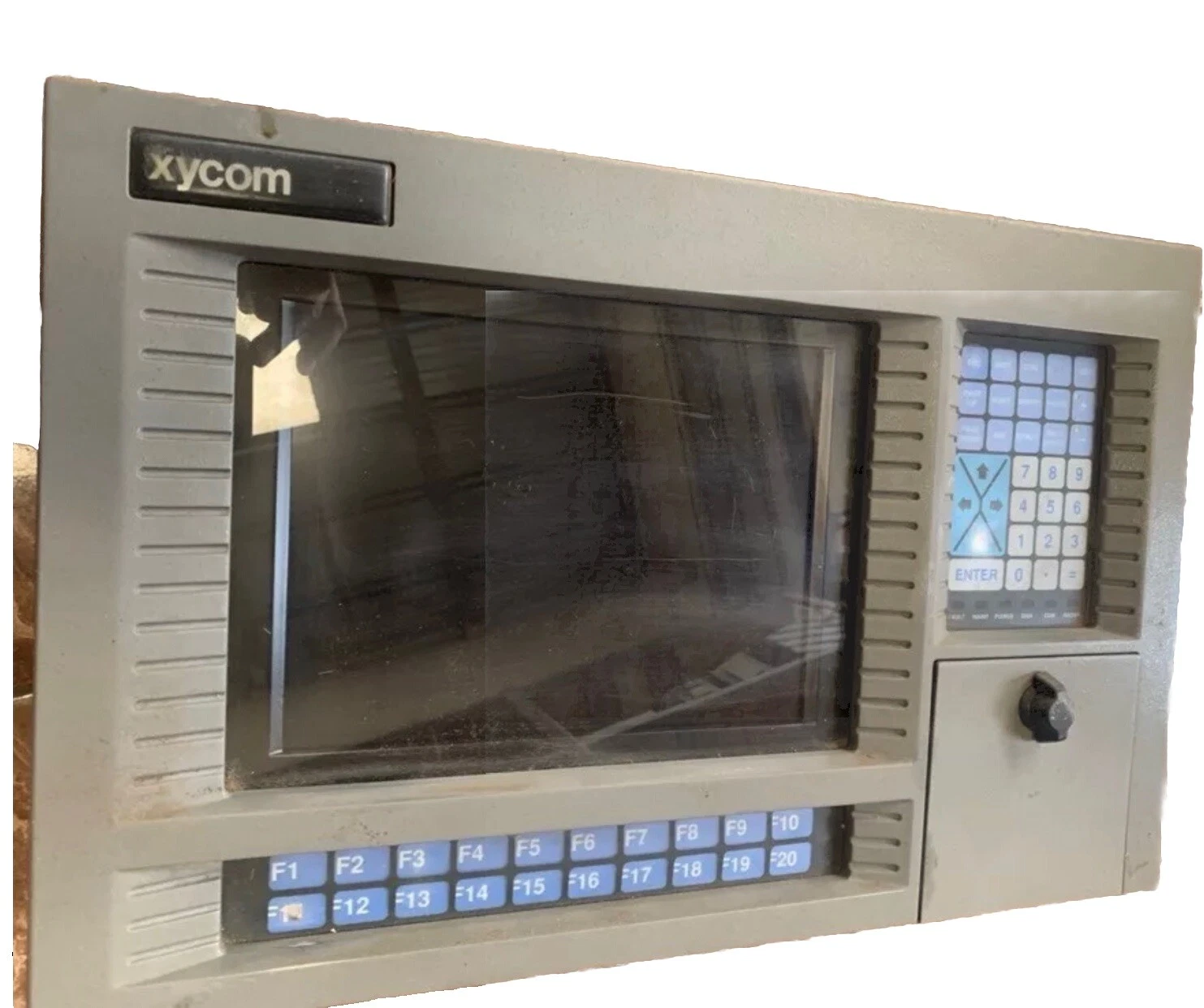
As an HMI device, 4860 A is mainly used for human-machine interaction in industrial automation systems, supporting graphical interface display, parameter settings, and device monitoring.
Technical parameters: 12 inch screen, 115/230V wide voltage input, compatible with 50/60Hz frequency, durable design suitable for industrial environments.
Product positioning and technical specifications
System compatibility:
The communication interface of 4860 A (such as RS-232/422) needs to be matched with the existing PLC or control system. If used for old systems, it is recommended to test protocol compatibility in advance (such as Modbus RTU).
If the original system relies on XYCOM specific software, software compatibility needs to be evaluated when migrating to Pro Face, and some features may need to be redeveloped.
The Xycom 81625DA control board is a high-performance core control board designed specifically for industrial automation control scenarios. With its powerful computing capabilities and rich functional configurations, it plays a key role in industrial control systems. This control board can accurately achieve real-time monitoring, data acquisition and processing, and logical control of industrial equipment. It is widely used in industrial automation production lines, energy management systems, intelligent mechanical equipment and other fields, providing reliable guarantees for the efficient and stable operation of industrial production.
Specification parameters
Ethernet interface: supports high-speed and stable data transmission, facilitates communication with factory networks, upper computers, or other intelligent devices, enables remote monitoring and management, and meets the demand for device interconnection in the industrial Internet of Things era.
RS-232/485 serial port: suitable for connecting traditional industrial instruments, sensors, and actuators, widely supports industrial communication protocols such as Modbus and Profibus, achieves reliable serial communication between devices, and ensures stable data exchange between industrial field devices.
USB interface: convenient for external storage devices, used for program backup, data import and export; It can also be connected to devices such as keyboards and mice for easy on-site debugging and operation.
Input/output channel
Analog input channel: Supports multiple types of analog signals, such as voltage (0-10V, ± 10V, etc.), current (4-20mA), etc. The input accuracy can reach [specific accuracy, such as ± 0.1% FS], with high resolution, and can accurately collect weak signal changes in industrial sites.
Working Voltage: Supports a wide range of working voltage inputs, such as DC 12-24V, to adapt to complex and changing power supply conditions in industrial sites. It has overvoltage and undervoltage protection functions to ensure stable operation of the control board in voltage fluctuation environments.
Working temperature: The working temperature range is [-20 ℃ -70 ℃], which can work normally in harsh industrial environments such as high and low temperatures, meeting the requirements of different industrial scenarios for equipment environmental adaptability.
Size specifications: The dimensions are 200mm × 150mm × 20mm, with a compact design that is easy to install in places with limited space such as industrial control cabinets and equipment chassis.
Core functions
Real time control: Real time and precise control of industrial equipment based on preset control programs and algorithms. Whether it is the start stop of the production line, the action control of the robotic arm, or the opening and closing operation of valves, the Xycom 81625DA control board can quickly and accurately execute control instructions, ensuring that the industrial production process proceeds in an orderly manner according to the predetermined logic.
Data collection and processing: Real time collection of analog and digital data from various sensors and instruments, such as temperature, pressure, flow rate, position, and other information. Preprocess the collected data by filtering, amplifying, and converting it to improve its accuracy and stability. Then, use a powerful processor for deep analysis and computation, providing reliable decision-making basis for industrial control systems.
Fault diagnosis and warning: Built in intelligent fault diagnosis system, capable of real-time monitoring of the operation status of the control board itself and connected devices. Once an abnormal situation is detected, such as equipment failure, parameter exceeding limits, communication interruption, etc., an alarm will be immediately issued through sound and light alarms, communication interfaces to upload alarm information, etc., and detailed fault information will be recorded to facilitate technical personnel to quickly locate and troubleshoot the fault.
Communication and networking: With the support of rich communication interfaces and multiple communication protocols, high-speed data communication and networking functions with other devices, controllers, or upper computers can be achieved. Upload the collected data to the upper computer of the monitoring center for real-time monitoring and data analysis by operators; Receive control instructions and parameter settings issued by the upper computer to achieve remote monitoring and management. In addition, it can also interact and collaborate with other intelligent devices to build intelligent industrial control systems.
Working principle
In the industrial production process, sensors and other equipment transmit the collected analog and digital signals to the Xycom 81625DA control board through corresponding input channels. The input interface on the control board receives and preliminarily processes signals, such as signal conditioning, level conversion, etc., and then transmits the processed signals to the core processor.
The processor analyzes and calculates data based on pre written control programs and algorithms to determine whether the current production status is normal and whether control adjustments are needed for the equipment. If control is required, the processor converts control instructions into corresponding electrical or digital signals through output channels, transmits them to the actuator, drives the actuator to act, and achieves control of industrial equipment.
At the same time, the control board interacts with other devices or the upper computer through communication interfaces for data exchange. On the one hand, the collected data and equipment operation status information are uploaded to the monitoring center or upper computer for real-time monitoring and data analysis by operators; On the other hand, it receives instructions and parameter settings from the upper computer or other devices, adjusts the working state and control strategy according to the instructions, and ensures the coordinated operation of the entire industrial automation system
Throughout the entire working process, the built-in fault diagnosis module of the control board monitors the working status of itself and connected devices in real time. Once an abnormality is detected, an alarm mechanism is immediately triggered to ensure the safe and stable operation of the system.
Key advantages
High reliability and stability: using industrial grade components and strict manufacturing processes, after multiple rigorous tests and verifications, it has excellent anti-interference ability and environmental adaptability. It can operate stably for a long time in harsh industrial environments such as high temperature, humidity, vibration, and strong electromagnetic interference, effectively reducing equipment failure rates and maintenance costs, and ensuring the continuity of industrial
Production.
Powerful functional integration: Highly integrated with various functions such as data acquisition, processing, control, and communication, it can meet the needs of complex industrial control scenarios without the need for additional modules, simplify system architecture, and reduce system costs and complexity.
Flexibility and Scalability: The rich input/output channels and communication interfaces, as well as the scalable hardware architecture, enable the control board to flexibly adapt to different industrial application scenarios and production needs. Users can easily add or replace functional modules such as data acquisition modules, communication modules, etc. according to their actual needs, to achieve system upgrades and expansions.
Easy to use and maintain: Provides standardized interfaces and communication protocols for easy connection and integration with other devices. The control board is equipped with status indicator lights, which can intuitively display the working status and fault information, making it easy for technicians to quickly locate and troubleshoot faults. In addition, comprehensive technical documentation and development tools enable engineers to quickly get started with programming and debugging work.
Precautions
Installation environment: The control board should be installed in a dry, well ventilated, and dust-free environment, avoiding installation in places with corrosive gases, large amounts of dust or water vapor, and preventing electronic components from being corroded or damaged. The installation location should ensure good heat dissipation conditions to avoid affecting the performance and lifespan of the control board due to high temperature.
Wiring operation: When wiring the control board, it is necessary to ensure that the equipment is in a power-off state and strictly follow the wiring diagram and instructions to avoid damage to the control board or system failure caused by wiring errors. For analog signals, shielded cables should be used for connection and grounding treatment should be done to reduce signal interference.
Static protection: When installing, disassembling, or maintaining the control board, operators must wear protective equipment such as anti-static wristbands to avoid damage to the precision electronic components on the control board caused by human static electricity. Try to avoid direct contact with electronic components and circuits during the operation process.
Software management: Regularly update and maintain the software system of the control board, promptly fix vulnerabilities and optimize performance. When performing software operations such as program downloads and parameter settings, it is necessary to follow the steps in the operation manual to avoid program errors or system failures caused by improper operation. At the same time, do a good job in data backup to prevent data loss.
The Allen Bradley 91195A circuit board is a programmable circuit board designed specifically for A-B Xycom terminals, aimed at providing efficient and reliable hardware support for industrial automation control systems. With its powerful programming capabilities and high compatibility with Xycom terminals, it can accurately control industrial equipment, collect and process data, and is widely used in industrial automation production lines, energy management, mechanical equipment control and other fields, helping enterprises improve production efficiency and automation level.
Brand background
(1) Allen Bradley
Allen Bradley (A-B for short) is a core brand under Rockwell Automation, with over a hundred years of history in the field of industrial automation. A-B is known for its innovative technology, excellent product quality, and comprehensive solutions. Its products include programmable logic controllers (PLCs), human-machine interfaces (HMI), frequency converters, etc., and are widely used in the global manufacturing industry. It holds an important position in industries such as automotive, food and beverage, pharmaceuticals, and power, and is a trusted brand in the field of industrial automation.
(2) Xycom
Xycom also has a profound technical accumulation in the fields of industrial automation and embedded computing, focusing on providing high-performance computer hardware and solutions for industries such as industry, aerospace, and defense. Xycom’s products are renowned for their high reliability, powerful functionality, and excellent environmental adaptability. Together with Allen Bradley, they are driving the development of industrial automation technology.
Technical specifications
Processor performance: Equipped with [specific processor model], it has powerful data processing and computing capabilities, can quickly execute complex control programs and algorithms, ensuring the efficient operation of industrial equipment. For example, when processing large amounts of sensor data and executing real-time control instructions, it can respond quickly to ensure the continuity of the production process. .
Communication interface
Ethernet interface: supports high-speed and stable data transmission, facilitates communication with factory networks, upper computers, or other intelligent devices, and enables remote monitoring and management. Through Ethernet, technicians can remotely upload and download programs, and view the real-time running status of devices.
RS-232/485 serial port: suitable for connecting traditional industrial instruments, sensors, and actuators, widely supports industrial communication protocols such as Modbus and Profibus, achieves reliable serial communication between devices, and ensures stable data exchange between industrial field devices.
USB interface: convenient for external storage devices, used for program backup, data import and export; It can also be connected to devices such as keyboards and mice for easy on-site debugging and operation.
Working voltage: Supports a wide range of DC voltage inputs, such as DC 12-24V, to adapt to complex and changing power supply conditions in industrial sites. It has overvoltage and undervoltage protection functions to ensure stable operation of the circuit board.
Working temperature: The working temperature range is [-20 ℃ -70 ℃], which can operate normally in harsh industrial environments such as high and low temperatures, and adapt to the needs of different industrial scenarios.
Size specifications: The dimensions are [length x width x height, such as 200mm x 150mm x 20mm], with a compact design that is easy to install in places with limited space such as industrial control cabinets and equipment chassis.
Core functions
Programmable Control: Supports multiple programming languages such as Ladder Logic, Structured Text (ST), Function Block Diagram (FBD), etc., making it convenient for engineers to write programs according to different industrial control requirements. Through programming, it is possible to achieve logical control, sequential control, motion control, and other functions of industrial equipment to meet diverse production process requirements.
Data collection and processing: Real time and accurate collection of analog and digital data from various sensors in the industrial field, and pre-processing operations such as filtering, amplification, and conversion of the collected data to improve its accuracy and stability. Then, through powerful processors for deep analysis and computation, reliable data support is provided for production decisions.
Equipment monitoring and fault diagnosis: Real time monitoring of the operating status of connected devices, and fault detection and analysis of devices through built-in diagnostic programs. Once device abnormalities are detected, such as parameter overruns, equipment failures, etc., alarm information is immediately uploaded through the communication interface and detailed fault information is displayed on the Xycom terminal for technicians to quickly locate and troubleshoot.
System integration and collaboration: With rich communication interfaces and support for multiple industrial communication protocols, seamless integration can be achieved with A-B Xycom terminals and other industrial equipment such as PLCs, HMIs, frequency converters, etc. Through data exchange and collaborative work, a complete industrial automation control system is constructed to achieve automation and intelligent management of the production process.
Working principle
During the industrial production process, sensors and other devices transmit the collected analog and digital signals to the Allen Bradley 91195A circuit board through corresponding input channels. The signal conditioning circuit inside the circuit board performs preliminary processing on the input signal, such as filtering, amplification, level conversion, etc., and then transmits the processed signal to the core processor.
The processor analyzes and calculates data based on pre written control programs to determine whether the current production status is normal and whether control adjustments are needed for the equipment. If control is required, the processor converts the control instructions into corresponding electrical or digital signals through the output channel, transmits them to the actuator, drives the actuator to act, and achieves control of the device.
At the same time, the 91195A circuit board interacts with A-B Xycom terminals and other devices through communication interfaces for data exchange. On the one hand, the collected data and device operating status information will be uploaded to the Xycom terminal for real-time monitoring and data analysis by operators; On the other hand, it receives instructions and parameter settings from Xycom terminals or other devices, adjusts the working state and control strategy according to the instructions, and ensures the coordinated operation of the entire industrial automation system.
Throughout the entire working process, the fault diagnosis module of the circuit board monitors the working status of itself and connected devices in real time. Once an abnormality is detected, an alarm mechanism is immediately triggered to ensure the safe and stable operation of the system.
Key advantages
High compatibility: specifically designed for A-B Xycom terminals, it has extremely high compatibility with Xycom terminals and other A-B devices, enabling seamless integration, reducing the difficulty and risk of system integration, and improving system stability and reliability.
Powerful programming ability: Supports multiple popular industrial programming languages, flexible and convenient programming, and can meet industrial control needs of different levels of complexity. Both simple logic control and complex motion control and process control can be easily implemented through programming.
High reliability and stability: using industrial grade components and strict manufacturing processes, after multiple rigorous tests and verifications, it has excellent anti-interference ability and environmental adaptability. It can operate stably for a long time in harsh industrial environments such as high temperature, humidity, vibration, and strong electromagnetic interference, effectively reducing equipment failure rates and maintenance costs.
Easy to maintain and upgrade: The modular design makes maintenance of the circuit board more convenient. In case of a malfunction, the faulty module can be quickly replaced, reducing downtime. At the same time, program updates and system upgrades can be easily carried out through communication interfaces to adapt to constantly changing production needs.
Precautions
Installation environment: The circuit board should be installed in a dry, well ventilated, and dust-free environment, avoiding installation in places with corrosive gases, large amounts of dust or water vapor, and preventing electronic components from being corroded or damaged. The installation location should ensure good heat dissipation conditions to avoid affecting the performance and lifespan of the circuit board due to high temperature.
Wiring operation: When wiring the circuit board, it is necessary to ensure that the equipment is in a power-off state and strictly follow the wiring diagram and instructions to avoid damage to the circuit board or system failure caused by wiring errors. For analog signals, shielded cables should be used for connection and grounding treatment should be done to reduce signal interference.
Static protection: When installing, disassembling, or maintaining circuit boards, operators must wear protective equipment such as anti-static wristbands to avoid damage to precision electronic components on the circuit board caused by human static electricity. Try to avoid direct contact with electronic components and circuits during the operation process.
Software management: Regularly update and maintain the software system of the circuit board, promptly fix vulnerabilities and optimize performance. When performing software operations such as program downloads and parameter settings, it is necessary to follow the steps in the operation manual to avoid program errors or system failures caused by improper operation. At the same time, do a good job in data backup to prevent data loss.
Similar model supplement
Allen Bradley 91196A Circuit Board: Another circuit board product in the same series that shares some similarities in functionality and architecture with 91195A, but may differ in processor performance, memory capacity, communication interface configuration, and other aspects. For example, 91196A may have faster data processing speed or more communication interfaces, making it suitable for industrial applications with higher performance requirements.
The Xycom 94354-001 display screen (94354001 8503 HMI front panel) is a high-performance display screen designed specifically for industrial human-machine interaction (HMI) scenarios. As a key interactive interface of industrial control systems, it combines intuitive operating experience with powerful data processing capabilities to achieve efficient information exchange between operators and industrial equipment and systems. This display screen is widely used in industrial automation production lines, energy management systems, mechanical equipment control and other fields, providing a convenient and reliable visual operation platform for monitoring, management and control of industrial production.
Brand background
Xycom has been deeply rooted in the fields of industrial automation and embedded computing for many years, and has become a trusted brand in the industry with its profound technological accumulation and continuous innovation. Its products are known for their high reliability, powerful functionality, and excellent environmental adaptability. They have long provided solutions for industries such as industry, aerospace, and defense that require high equipment stability. They have rich technological accumulation and a good market reputation in the field of industrial automation.
technical specifications
Display parameters
Resolution: 1024 × 768 pixels, capable of presenting delicate and clear images and text information, ensuring accurate and error free display of various industrial data and operation interfaces.
Display technology: It has the characteristics of high brightness and high contrast, and can still ensure clear and visible screen content under complex lighting conditions in industrial sites (such as strong direct light and dim environments).
Touch performance
Touch control method: sensitive and precise operation, fast response speed, even if the operator wears gloves, they can easily achieve touch control operation, meeting the diverse operational needs of industrial sites.
Touch lifespan: After rigorous testing, the touch panel has an ultra long lifespan and can withstand millions of clicks and sliding operations, ensuring stability and reliability during long-term use in industrial production.
Interface Configuration
Communication Interface: Equipped with a variety of communication interfaces, including Ethernet interface (supporting high-speed data transmission, facilitating communication with industrial networks, upper computers, or other intelligent devices for remote monitoring and data exchange), RS-232/485 serial port (suitable for connecting traditional industrial instruments, PLCs, and other devices, supporting industrial communication protocols such as Modbus and Profibus), USB interface (convenient for external storage devices, keyboards, mice, etc., used for data import and export, program updates, and extended device connections).
Work environment
Working voltage: Supports a wide range of DC voltage inputs, such as DC 18-36V, to adapt to the complex and changing power supply conditions in industrial sites. It has overvoltage and undervoltage protection functions, effectively ensuring the stable operation of the display screen.
Working temperature: The working temperature range is [-20 ℃ -70 ℃], which can work normally in harsh industrial environments such as high and low temperatures
Protection level: up to IP65 or other protection level standards, with dustproof and waterproof capabilities, can effectively resist the invasion of pollutants such as dust, oil, water droplets, etc. in industrial sites, ensuring the long-term stable operation of the display screen in harsh environments.
install
Installation method: Supports various installation methods such as panel embedded installation, wall mounted installation, etc. The installation process is simple and convenient, and can be flexibly selected according to actual application scenarios
Core functions
Data visualization display: Display various types of data in the industrial production process (such as equipment operating parameters, production progress, quality inspection data, etc.) in real-time on the screen in the form of intuitive charts (such as line charts, bar charts, pie charts), dashboards, text, etc., helping operators quickly understand the production status, discover problems in a timely manner, and make decisions.
Human computer interaction operation: Through touch screens or external input devices such as keyboards and mice, operators can easily control industrial equipment and systems, such as setting device operating parameters, starting/stopping devices, switching production modes, etc. The operation interface adopts a graphical design, which is user-friendly and the operation process is simple and easy to understand, reducing the learning cost of operators.
Alarm and prompt function: Built in alarm system. When industrial equipment or systems encounter abnormal situations (such as parameter exceeding limits, equipment failure), the display screen immediately issues an alarm in the form of sound and light alarm, pop-up prompt, etc., while displaying detailed alarm information (such as alarm type, occurrence time, location, etc.), reminding operators to handle it in a timely manner to avoid accidents.
Data Storage and Management: Supports local data storage, allowing key data in industrial production processes (such as historical operating parameters, alarm records, etc.) to be stored in built-in or external storage devices on the display screen, facilitating later queries, analysis, and traceability. At the same time, data can be uploaded to the upper computer or cloud server through communication interfaces to achieve centralized management and remote access of data.
Multi language support: Supports switching between multiple language interfaces, such as Chinese, English, German, etc., to meet the usage needs of different regions and operators, making it easy for multinational enterprises or international industrial projects to apply.
XYCOM 8100-0272A Brown Output Sensor Board is a sensor output board designed specifically for industrial automation systems, aimed at achieving efficient acquisition, processing, and output of sensor signals. As a key component of industrial control systems, it can accurately obtain various sensor data and convert it into output signals suitable for subsequent equipment, ensuring the accuracy and real-time performance of data in industrial production processes. It is widely used in industrial scenarios that require precise monitoring and control, such as automated production lines, mechanical equipment monitoring, environmental parameter collection, etc.
Brand background
XYCOM has a profound technical accumulation and a good market reputation in the fields of industrial automation and embedded computing. For many years, the brand has been dedicated to providing high-performance and highly reliable computer hardware and solutions for industries such as industry, aerospace, and defense. With advanced technology, strict quality control, and a comprehensive service system, it has become a trusted partner for many industrial enterprises. Its products are known for their excellent stability, powerful functionality, and outstanding compatibility, and perform excellently in complex industrial environment applications.
Technical specifications
Sensor interface types: Supports multiple mainstream sensor interfaces, such as analog input interfaces (compatible with voltage and current sensors, such as 0-10V, 4-20mA signal input), digital input interfaces (supporting TTL/CMOS level standards), and can be compatible with connecting various industrial sensors such as temperature sensors, pressure sensors, displacement sensors, etc.
Communication interface: equipped with RS-232/485 serial port and Ethernet interface, supporting industrial communication protocols such as Modbus and Profibus, facilitating high-speed data communication and networking with other devices, achieving remote data transmission and monitoring.
Working voltage: Supports a wide range of DC voltage inputs, such as DC 18-36V, to adapt to the complex and changing power supply conditions in industrial sites. It has overvoltage and undervoltage protection functions, effectively ensuring the stable operation of the board.
Working temperature: The working temperature range is [-40 ℃ -85 ℃], which can work normally in harsh industrial environments such as high and low temperatures, meeting the strict requirements of industrial sites for equipment environmental adaptability.
Core functions
Sensor signal acquisition: Real time and accurate acquisition of analog and digital signals from various industrial sensors, capable of processing multiple sensor data simultaneously, ensuring comprehensive monitoring of industrial field parameters. For example, in chemical production, key parameters such as temperature and pressure of reaction vessels can be quickly collected.
Signal processing and conversion: Preprocess and convert the collected sensor signals, remove signal interference through filtering algorithms, enhance signal strength through amplification circuits, and convert analog signals into digital signals, providing accurate and stable inputs for subsequent data processing and control.
Data output and transmission: The processed sensor data is output to the target device in analog or digital form, and the data is uploaded to the industrial network or upper computer through a communication interface to achieve remote transmission and sharing of data, facilitating real-time monitoring of the industrial site status by operators.
Fault diagnosis and protection: Built in self diagnostic function, which can monitor the working status of the board and the connection status of sensors in real time. When a sensor malfunction, communication abnormality, or board malfunction is detected, the fault information is immediately reported through the indicator light alarm or communication interface for technicians to quickly locate and troubleshoot. In addition, it has functions such as short-circuit protection and overcurrent protection to ensure that the board is not damaged in abnormal situations.
Working principle
Sensors on industrial sites convert physical quantities such as temperature, pressure, displacement, etc. into electrical signals, which are then transmitted to the XYCOM 8100-0272A Brown Output Sensor Board through corresponding interfaces. After the input interface of the board receives the signal, the signal is first preprocessed by the signal conditioning circuit, such as filtering and amplification, to remove noise and interference from the signal and improve signal quality.
Next, the analog signal is converted into a digital signal through an analog-to-digital conversion (A/D) circuit, and the digital signal directly enters the logic processing unit of the board. The logic processing unit analyzes and processes the processed signals, performs data calibration, compensation, and other operations according to preset programs and algorithms to ensure the accuracy of the data.
The processed sensor data is partially output to connected devices through analog or digital output channels for controlling actuators or providing data input to other devices; The other part packages and uploads data to industrial networks or upper computers through communication interfaces according to communication protocols such as Modbus and Profibus, achieving remote transmission and centralized monitoring of data.
Throughout the entire process, the self diagnostic module of the board monitors the working status of each circuit and sensor connection in real time. Once any abnormalities are detected, the fault alarm mechanism is immediately triggered to ensure the safe and stable operation of the system.
Key advantages
High compatibility: Supports multiple types of sensor interfaces and communication protocols, seamlessly integrating with sensors and industrial equipment of different brands and specifications, greatly improving the versatility of the equipment and the flexibility of the system.
High precision and stability: Adopting high-precision signal processing circuits and advanced analog-to-digital conversion technology to ensure the accuracy and stability of sensor data acquisition. It can still work reliably in harsh industrial environments, effectively reducing data errors and system failure risks.
Easy to install and maintain: The board design is compact and easy to install, providing standardized interfaces and clear wiring labels for technicians to install and debug. At the same time, the improved fault diagnosis function and detailed technical documentation make maintenance work more convenient and efficient, reducing maintenance costs and time.
Flexible Scalability: Rich input/output channels and communication interfaces allow users to flexibly expand system functionality according to actual needs. For example, increasing the number of sensors or connecting more control devices can meet the needs of industrial production scale expansion or functional upgrading.
Precautions
Installation environment: The board should be installed in a dry, well ventilated, and dust-free environment, avoiding installation in places with corrosive gases, large amounts of dust or water vapor, to prevent electronic components from being corroded or damaged. At the same time, it is necessary to ensure that the installation location has good heat dissipation conditions to avoid affecting the performance and lifespan of the board due to high temperatures.
Wiring operation: When wiring the board, it is necessary to ensure that the equipment is in a power-off state and strictly follow the wiring diagram and instructions to avoid damage to the board or system failure caused by wiring errors. For analog signals, shielded cables should be used for connection and grounding treatment should be done to reduce signal interference.
Static protection: When installing, disassembling, or maintaining the board, operators must wear protective equipment such as anti-static wristbands to avoid damage to the precision electronic components on the board caused by human static electricity. Try to avoid direct contact with electronic components and circuits during the operation process.
Communication settings: When setting communication parameters (such as communication protocol, baud rate, device address, etc.), make sure they are consistent with the parameters of the connected device, otherwise it may cause communication failure. During system operation, if communication parameters need to be changed, the relevant equipment should be stopped before setting the parameters.
Similar model supplement
XYCOM 8100-0273A: Another sensor output board in the same series, which has some similarities in functionality and architecture with 8100-0272A, but may differ in the number of sensor interfaces, signal processing accuracy, or output channel configuration. It is suitable for industrial application scenarios with slightly different functional requirements.
Application scenarios
Industrial automation production line: In automated production lines such as automobile manufacturing, electronic assembly, and food processing, it is used to collect various parameters during the production process (such as component size, assembly position, production speed, etc.), providing data support for the automation control and quality monitoring of the production line, ensuring the efficiency, accuracy, and stability of the production process and product quality.
Mechanical equipment status monitoring: Real time monitoring of equipment operating parameters (such as vibration, temperature, speed, etc.) in various types of mechanical equipment such as CNC machine tools, printing machinery, packaging machinery, etc. By analyzing sensor data, equipment failure warning and predictive maintenance can be achieved, reducing equipment downtime and improving equipment reliability and service life.
Energy and Environmental Monitoring: Used in energy industries such as electricity, petroleum, and chemical engineering, as well as in the field of environmental monitoring, it is used to collect key parameters (such as flow rate, pressure, electricity consumption, etc.) and environmental parameters (such as temperature, humidity, air quality, etc.) in the energy production process, providing accurate data for energy management and environmental monitoring, and helping to achieve energy optimization and environmental protection goals.
Intelligent buildings and building automation: In intelligent buildings and building automation systems, indoor and outdoor environmental parameters (such as temperature, humidity, light intensity, etc.), equipment operating status (such as the working status of air conditioning, elevators, lighting equipment) and other data are collected to achieve intelligent control and energy management of building equipment, improve building comfort and energy utilization efficiency.
Proper grounding is essential to all safe electrical installations. Applicable Fed eral/State/Provincial codes provide data such as the size and types of conductors,color codes, and connections necessary for safe grounding of electrical components.
The code specifies that a grounding path must be permanent (no solder), continuous,and able to safely conduct the ground-fault current in the system with minimal im pedance.
The following practices should be observed:
• Terminate protective Earth Ground to the enclosure chassis near the point of entry.
In a noisy environment, local ground rod may be necessary.
• All electrical racks or chassis and machine elements should be grounded to a central ground bus (a “star” ground bus is best).
• The enclosure should be properly grounded to the ground bus.
Make sure a good electrical connection is made at the point of contact with the enclosure.
Line Voltage Considerations
The 9485/9487 DC power supply is built to sustain line fluctuations of 20 – 25 VDC and still allow the system to function within its operating margin.
As long as the in coming voltage is adequate, the power supply provides all the logic voltages neces
sary to support the processor, memory, and I/O.
Creating a Power Cable
You must create a power cable to supply power to the 9485/9487.
You need the fol lowing materials:
• Three-position power connector (supplied)
• 14 (1.6 mm), 16 (1.3 mm), or 18 (1.0 mm) gage solid or stranded copper wire within a braid/foil shielded cable, rated 80° C or better
Perform the following steps to create the cable:
1. Cut the wire cable to the desired length. It is good practice to make the protective earth ground wire ¼-inch (6.35 mm) to ½-inch (12.7 mm) longer than the +VIN and -VIN wires.
2. Strip .39-inch (10 mm) of insulation from the end of the cable. No bare wire should be exposed when the cable is connected to the workstation.
3. Tin the wire ends with solder if using stranded wire.
This keeps the wire from fraying.
4. Insert three wire ends of the power cable into the three holes of the block plug,as shown
The Ground (PE) +VIN and -VIN wires should be inserted into the corresponding holes (again, refer to Figure 2). Be sure that no bare wires are exposed.
5. Tighten the three screws above the wires to hold them firmly in place.
Product Overview
Xycom 9485 Automatic CY is a high-performance product under the Xycom brand that focuses on the field of automation. It aims to provide efficient and reliable automation solutions for industrial production, equipment control, and other scenarios. With advanced technological architecture and powerful functional features, it can achieve precise control and monitoring of complex industrial processes, help enterprises improve production efficiency, reduce operating costs, and play an important role in the process of industrial automation.
Key advantages
High reliability and stability: using industrial grade components and strict manufacturing processes, after multiple rigorous tests and verifications, it has excellent anti-interference ability and environmental adaptability. It can operate stably for a long time in harsh industrial environments such as high temperature, humidity, vibration, and strong electromagnetic interference, effectively reducing equipment failure rates and maintenance costs, and ensuring production continuity.
Flexibility and Scalability: With rich input/output channels and communication interfaces, as well as modular design architecture, the 9485 Automatic CY can flexibly adapt to different industrial application scenarios and production needs. Users can easily add or replace functional modules such as data acquisition modules, communication modules, etc. according to their actual needs, to achieve system upgrades and expansions.
Intelligence and ease of use: Integrating advanced intelligent control algorithms and fault diagnosis technology, the operating interface is simple and intuitive, supporting graphical programming and parameter settings, reducing the threshold for use, and facilitating engineers in program development and debugging. At the same time, we provide comprehensive technical documentation and training services to facilitate users in quickly mastering the use and maintenance methods of the equipment.
Precautions
Installation environment: The equipment should be installed in a dry, well ventilated, and dust-free environment, avoiding installation in places with corrosive gases, large amounts of dust or water vapor, and preventing electronic components from being corroded or damaged. The installation location should ensure good heat dissipation conditions to avoid affecting equipment performance and lifespan due to high temperatures.
Wiring operation: When wiring equipment, it is necessary to ensure that the equipment is in a power-off state and strictly follow the wiring diagram and instructions to avoid equipment damage or system failure caused by wiring errors. For analog signals, shielded cables should be used for connection and grounding treatment should be done to reduce signal interference.
Static electricity protection: When installing, disassembling, or maintaining equipment, operators must wear protective equipment such as anti-static wristbands to avoid damage to precision electronic components on the equipment caused by human static electricity. Try to avoid direct contact with electronic components and circuits during the operation process.
Software management: Regularly update and maintain the software system of the device, promptly fix vulnerabilities and optimize performance. When performing software operations such as program downloads and parameter settings, it is necessary to follow the steps in the operation manual to avoid program errors or system failures caused by improper operation. At the same time, do a good job in data backup to prevent data loss.
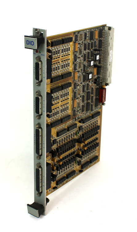
The XVME-244 Digital I/O Module is an isolated 64-channel, digital I/O module designed for use in
VMEbus systems.
Thirty-two input channels and thirty-two output channels are provided, arranged in groups of eight, optically-isolated from the others and from the VMEbus circuitry.
The 64 I/O channels are arranged to form eight, byte wide I/O registers. The I/O registers are addressed consecutively, allowing the input and output channels to be accessed as either bytes or words.
To add to the integrity of the system, default initialization disables all outputs both during system power-up and during a software reset or SYSFAIL.
This module is ideally suited for interfacing to pushbutton or relay contacts.
It contains input debouncing circuitry which eliminates the effects of contact bounce from such inputs.
The XVME-244 provides four filtered inputs for those applications where filtering is desired for a particular input.
One filtered input is provided for each input group as a read-only register containing the state of
the filtered input.
These registers may be accessed as bytes or as 16-bit words.
Features
Outputs
• 32 optically-isolated digital output channels
• Outputs to 30 V and 400 mA
• 300 VDC optical isolation group-to-group and
1000 V group-to-VMEbus
• Hardware initialization of outputs at power-up
• Outputs are software-readable
• Transient protection on all outputs
Inputs
• 32 digital input channels
• Input voltage range 10-35 VDC
• Input debouncing circuitry
• 35 VDC reverse bias protection
• 300 VDC optical isolation group-to-group and
1000 V group-to-VMEbus
Applications
Outputs
• Control valves
• Solid-state relays
• Alarm interface
• Indicator lamps
Inputs
• Limit switches
• Push buttons or panel switches
• Proximity switches
• Alarm trips
• Photo detector switches
Product Overview
Xycom XVME-244 DIO Digital Input/Output Card Module 70244-001 is a digital input/output card module designed based on the VME Bus standard, specifically designed for industrial automation control, data acquisition, and monitoring systems. As a key component of signal interaction in industrial control systems, it can efficiently collect and output digital signals, accurately control various actuators, ensure the stable operation of industrial production processes, and is widely used in fields such as automotive manufacturing, electronic assembly, and energy management.
Brand background
Xycom has been deeply involved in the fields of industrial automation and embedded computing for many years, renowned for providing high-performance and highly reliable hardware products. With its profound technical accumulation and strict quality control, its products have gained wide recognition and trust in industries such as industry, aerospace, etc. that require extremely high stability and accuracy. Xycom continues to innovate and is committed to meeting the increasingly complex application needs of industrial customers, making it the preferred partner for many industrial enterprises.
Core functions
Digital signal acquisition: Quickly and accurately collect various digital signals from industrial sites, such as equipment start stop status, limit switch signals, sensor trigger signals, etc. Real time processing and caching of collected signals to provide accurate equipment operating status information for the control system, in order to make timely control decisions.
Digital signal output: According to the instructions of the control system, the digital signal is accurately output to the actuator to achieve on/off control of the equipment. For example, controlling the start and stop of motors, opening and closing of valves, and turning on and off indicator lights to ensure that industrial production processes proceed in an orderly manner according to preset logic.
Signal isolation and protection: Through optoelectronic isolation technology, input/output signals are effectively isolated from external circuits to prevent external electrical interference from affecting the module and control system. At the same time, it has overcurrent and short-circuit protection functions to enhance the reliability and durability of the module and extend the service life of the equipment.
Communication and Collaboration: Supports communication with other devices on the VME Bus bus, uploads collected digital signals to the main controller or upper computer, and receives control instructions from the main controller to achieve collaborative work with the entire industrial control system, ensuring consistency and stability of system operation.
Precautions
Installation environment: During installation, a dry, well ventilated, and dust-free environment should be selected to avoid installation in places with corrosive gases, large amounts of dust or water vapor, and to prevent electronic components from being corroded or damaged. At the same time, it is necessary to ensure that the installation location has good heat dissipation conditions to avoid affecting the performance and lifespan of the module due to high temperatures.
Wiring operation: When wiring the module, it is necessary to ensure that the equipment is in a power-off state and strictly follow the wiring diagram and instructions to avoid module damage or system failure caused by wiring errors. For input signals, it is necessary to ensure that the voltage level of the signal source matches the input requirements of the module; For output signals, attention should be paid to the rated voltage and current of the load to avoid overload.
Static protection: When installing, disassembling, or maintaining modules, operators must wear protective equipment such as anti-static wristbands to avoid damage to the precision electronic components on the module caused by human static electricity. During the operation, direct contact with electronic components and circuits should be avoided as much as possible.
Communication settings: When communicating with other devices on the VME Bus bus, ensure that the communication parameters of the module (such as address, baud rate, etc.) are consistent with other devices, otherwise it may cause communication failure. During system operation, if communication parameters need to be changed, the relevant equipment should be stopped before setting the parameters
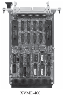
The Xycom Automation XVME-400 and XVME-401 Quad Serial I/O Modules are single-high, single-wide VMEbus modules that provide a VMEbus system with four serial communication channels.
The XVME-400 and XVME-401 differ only in their communication interface: the XVME-400 provides four RS-232C serial ports, while the XVME-401 provides four RS-422A/RS-485 serial ports.
Both modules contain two Z8530 Serial Communica tion Controller (SCC) chips which provide a variety of communication modes, including asynchronous, byte synchronous, and bit-oriented protocols.
Each channel is independently programmable and has its own baud rate generator and modem signal controls.
The VMEbus interface directly maps the Z8530 SCC chips into the short I/O address space, starting on a jumper-selected 1 Kbyte boundary.
The modules can also be jumpered to generate an interrupt on any of the seven VMEbus interrupt levels.
The two Z8530 SCC chips can generate a total of 16 different interrupt vectors.
For applications not allowing I/O to be routed out the front panel, the XVME-490 and XVME-491 offer the same functionality as the XVME-400 and XVME-401.
In a 6U form factor, the I/O is routed via the VMEbus P2 connector on the back of the board
Features
• Four serial ports
• Single (3U) size (XVME-400/401) or
double (6U) size (XVME-490/491)
• Asynchronous, monosynchronous, bisynchronous,
HDLC, SDLC operation
• Zilog Z8530 Serial Communication Controller
• Modem control
• RS-232C or RS-422A/RS-485-compatible
• Independent baud rate generators for each signal
channel
Applications
• Terminal or modem interface
• Serial printer interface
Hardware Specifications
Number of Channels 4
Serial Device
Zilog Z8530 SCC
Level Compatibility
XVME-400/490
XVME-401/491
Maximum Baud Rate
Internal, async
Internal, sync
External, async
External, sync
RS-232C
RS-422A/485
57.6 Kbaud
500 Kbaud
57.6 Kbaud
500 Kbaud
Modem Control Signals
XVME-400/401/490 RTS, CTS, DCD, DTR
XVME-491
RTS, CTS, DCD
Power Requirements
XVME-400/490
XVME-401/491
+5 V @ 1.1 A typ., 1.3 A max.
+12 V @ 100 A typ.,110 A max.
+5 V @ 1.4 A typ., 1.6 A max.
VMEbus Compliance
• Complies with VMEbus Specification, IEEE 1014
• A16:D08(O) DTB Slave
• Interrupter I(1)-I(7)(STAT), ROAK
• Interrupt vector D08(O)(DYN)
• Form Factor:- XVME-401 and XVME-401: SINGLE
3.9″ × 6.3″ (99.06 mm × 160.02 mm)- XVME-490 and XVME-491: DOUBLE
9.2″ × 6.3″ (233.68 mm × 160.02 mm)
Environmental Specifications
Hardware Specifications
Number of Channels 4
Serial Device
Zilog Z8530 SCC
Level Compatibility
XVME-400/490
XVME-401/491
Maximum Baud Rate
Internal, async
Internal, sync
External, async
External, sync
RS-232C
RS-422A/485
57.6 Kbaud
500 Kbaud
57.6 Kbaud
500 Kbaud
Modem Control Signals
XVME-400/401/490 RTS, CTS, DCD, DTR
XVME-491
RTS, CTS, DCD
Power Requirements
XVME-400/490
XVME-401/491
+5 V @ 1.1 A typ., 1.3 A max.
+12 V @ 100 A typ.,110 A max.
+5 V @ 1.4 A typ., 1.6 A max.
VMEbus Compliance
• Complies with VMEbus Specification, IEEE 1014
• A16:D08(O) DTB Slave
• Interrupter I(1)-I(7)(STAT), ROAK
• Interrupt vector D08(O)(DYN)
• Form Factor:- XVME-401 and XVME-401: SINGLE
3.9″ × 6.3″ (99.06 mm × 160.02 mm)- XVME-490 and XVME-491: DOUBLE
9.2″ × 6.3″ (233.68 mm × 160.02 mm)
Ordering Information
XVME-400 4 Channel RS-232C Serial I/O
XVME-401 4 Channel RS-422A Serial I/O
XVME-931 2 Channel RS-232C Cable for
XVME-400
XVME-932 2 Channel RS-422A/485 Cable for
XVME-401
XVME-490 6U Version of XVME-400 with I/O
Routed to the VMEbus P2 Connector
XVME-491 6U Version of XVME-401 with I/O
Routed to VMEbus P2 Connector
Product Overview
XYCOM XVME-400 70400-001 card is a high-performance board designed based on the VMEbus architecture, specifically designed for industrial automation control systems, data acquisition systems, and complex industrial monitoring scenarios. It highly integrates multiple functions, efficiently processes various types of data, accurately controls equipment operation, plays a key role in industrial production processes, and helps improve production efficiency and product quality.
Precautions
Installation environment: The card should be installed in a dry, well ventilated, and dust-free environment, avoiding installation in places with corrosive gases, large amounts of dust or water vapor, to prevent electronic components from being corroded or damaged. At the same time, ensure that the installation location has good heat dissipation conditions to avoid affecting the performance and lifespan of the card due to high temperatures. The installation process must be operated according to the requirements of the installation manual, ensuring that the card is tightly connected to the slot to prevent poor contact from causing equipment failure.
Static protection: When installing, disassembling, or maintaining the card, operators must wear protective equipment such as anti-static wristbands to avoid damage to the precision electronic components on the card caused by human static electricity. Try to avoid direct contact with electronic components and circuits during the operation process. If contact is necessary, release static electricity from the body first.
Power management: Strictly supply power within the working voltage range specified by the card to ensure power stability and purity. Using inferior or non compliant power sources may cause the card to malfunction or even damage the board. It is recommended to equip dedicated power filters and voltage stabilizing devices to reduce the impact of power fluctuations and interference on the card.
Software operation: When performing software operations such as program downloads and parameter settings, it is necessary to follow the steps in the operation manual to avoid program errors or system failures caused by improper operation. Before updating software versions, it is recommended to back up important data and programs to prevent data loss. At the same time, regularly maintain and update the software system of the card to achieve better performance and security.
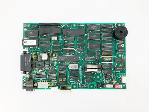
ADEPT TECH/XYCOM 70244-702 10330-00800 PC Board is a high-performance printed circuit board designed specifically for industrial automation and control systems. It is built on advanced industrial standard architecture, aiming to provide stable data processing, efficient communication capabilities, and precise control functions for industrial equipment. Whether in automated production lines, precision machinery equipment control, or complex industrial monitoring systems, this PC board can ensure the stable operation of industrial systems with excellent performance and reliable stability.
Core functions
Data collection and processing: capable of real-time collection of analog and digital data from various sensors, instruments, and other devices, such as temperature, pressure, flow rate, position, and other information. Preprocess the collected data by filtering, amplifying, and converting it to improve its accuracy and stability. Then, use a powerful processor for rapid analysis and computation, providing reliable decision-making basis for industrial control systems. For example, in an automated production line, the operating parameters of production equipment can be collected in real time, and through analysis and processing, the operating status of the equipment can be adjusted in a timely manner to ensure product quality and production efficiency.
System control and coordination: As the core component of industrial control systems, responsible for coordinating and managing the operation of various equipment and modules in the system. According to the preset program and control logic, send precise control instructions to the executing mechanism to achieve precise control of equipment such as motors, valves, and robotic arms, ensuring that the industrial production process proceeds smoothly according to the predetermined process. At the same time, it can monitor the operating status of the equipment in real time. Once abnormal situations are detected, such as equipment failure, parameter exceeding limits, etc., corresponding protective measures such as alarm and shutdown should be taken immediately to avoid accidents.
Communication and networking: With rich communication interfaces and supported multiple communication protocols, high-speed data communication and networking functions with other devices, controllers, or upper computers can be achieved. Upload the collected data to the upper computer of the monitoring center for real-time monitoring and data analysis by operators; Receive control instructions and parameter settings issued by the upper computer to achieve remote monitoring and management. In addition, it can also interact with other intelligent devices for data exchange and collaborative work, build intelligent industrial control systems, and improve the automation and intelligence level of industrial production.
Working principle
When sensors and other devices in the industrial field collect data, the data is transmitted to the 70244-702 10330-00800 PC board through the corresponding interface. The input interface on the PC board receives and preliminarily processes data, such as signal conditioning, level conversion, etc., and then transmits the data to the processor. The processor performs deep analysis, computation, and processing of data based on pre written programs and algorithms, to determine whether control or adjustment of the device is necessary. If necessary, the processor converts control instructions into corresponding electrical or digital signals through the output interface, sends them to the actuator, drives the actuator to act, and achieves control of industrial equipment.
Throughout the process, the PC board also interacts with other devices through communication interfaces for data exchange. On the one hand, upload the processed data to other devices or upper computers to achieve data sharing and remote monitoring; On the other hand, it receives instructions and parameters from other devices or upper computers, adjusts the working state and control strategy according to the instructions, and ensures the coordinated operation of the entire industrial control system. At the same time, the built-in self diagnostic module of the PC board will monitor its own operating status in real time. Once a fault or abnormality is detected, an alarm signal will be immediately sent out through the indicator light or communication interface, making it convenient for technicians to troubleshoot and repair.
Key advantages
High reliability: using industrial grade components and strict manufacturing processes, after multiple rigorous tests and verifications, it has excellent anti-interference ability and stability. Being able to operate stably for a long time in harsh industrial environments such as high temperature, humidity, vibration, and strong electromagnetic interference greatly reduces equipment failure rates and maintenance costs, ensuring the continuity and stability of industrial production.
Powerful scalability: With rich communication interfaces and scalable hardware architecture, this PC board can be easily integrated with various industrial equipment and modules. Users can flexibly add or replace functional modules according to their actual needs, such as data acquisition modules, communication modules, storage modules, etc., to meet the diverse needs of different industrial application scenarios and facilitate system upgrades and expansions.
Easy to develop and debug: Supports multiple commonly used programming languages and development environments, such as C, C++, Python, etc., making it convenient for engineers to develop and debug programs. At the same time, providing comprehensive software development tools and detailed technical documentation reduces development difficulty, improves development efficiency, and shortens project cycles.
Precautions
Installation environment: The PC board should be installed in a dry, well ventilated, and dust-free environment, avoiding installation in places with corrosive gases, large amounts of dust or water vapor, to prevent electronic components from being corroded or damaged. At the same time, it is important to ensure that the installation location has good heat dissipation conditions to avoid affecting the performance and lifespan of the PC board due to high temperatures. During the installation process, it is necessary to follow the requirements of the installation manual to ensure that the PC board is tightly connected to the slot and avoid equipment failure caused by poor contact.
Static protection: When installing, disassembling, or maintaining PC boards, operators must wear protective equipment such as anti-static wristbands to avoid damage to the precision electronic components on the board caused by human static electricity. During the operation, direct contact with electronic components and circuits should be avoided as much as possible. If contact is necessary, static electricity on the body should be released first.
Power management: Strictly follow the working voltage range specified by the PC board to ensure the stability and purity of the power supply. Using inferior or non compliant power sources may cause the PC board to malfunction or even damage the board. It is recommended to equip dedicated power filters and voltage stabilizing devices to reduce the impact of power fluctuations and interference on the PC board.
Software operation: When performing software operations such as program downloads and parameter settings, it is necessary to follow the steps in the operation manual to avoid program errors or system failures caused by improper operation. Before updating software versions, it is recommended to back up important data and programs to prevent data loss. At the same time, regularly maintain and update the software system of the PC board to achieve better performance and security.
Similar model supplement
ADEPT TECH/XYCOM 70245-703: Another PC board in the same series, which has some similarities in functionality and architecture with the 70244-702 10330-00800 PC board, but may have differences in processor performance, memory capacity, interface configuration, etc., making it suitable for industrial application scenarios with different performance requirements. For example, 70245-703 may be faster in data processing speed and more suitable for high-speed automated production lines with extremely high real-time requirements.