Call us 24/7uaedcs@163.com
Welcome to the official website of CNIACS Automation Technology Co., Ltd!
Call us 24/7uaedcs@163.com

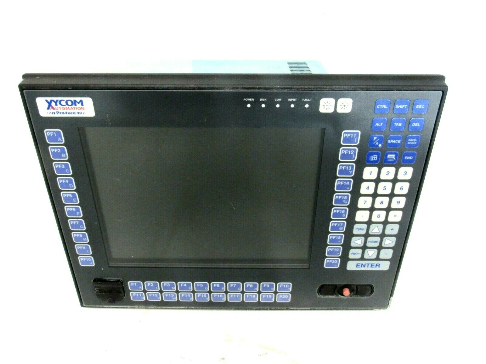
XYCOM XVME-956 Optical Disc Module XVME956

ODUCT OVERVIEW

The XVME-956 PC/AT family of products is designed to provide I/O expansion for Xycom’s XVME VMEbus PC/AT products.

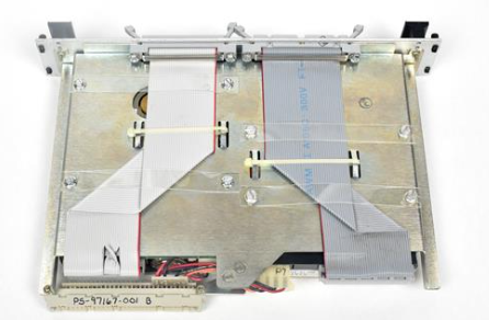
The XVME-956 consists of two sets of carrier cards and the accompanying daughter modules with either a PC/XT or PC/AT interface. 

When the daughter modules are installed onto a carrier, the resulting module occupies a single double-high VMEbus card slot. 

The XVME-956 is designed to operate with Xycom’s VMEbus PC/AT processor modules.

The XVME-956 provides the following features:

• PC/AT expansion I/O in a single VMEbus card slot

• Open architecture daughter modules available from Xycom and other vendors

• Pin and socket connector scheme (no card edge connectors)

• Convenient I/O front panel connections

The XVME-956 consists of carrier cards which drive the PC/AT signals from the host XVME PC/AT,and expansion modules which provide the various PC/AT I/O functions, such as Ethernet, Solid State

Disk, Serial I/O, and SCSI. The carrier cards (XVME-956/1 and XVME-956/12) are made to be compatible with Xycom’s line of VMEbus PC/AT products. The XVME-956/12 is for use with the Xycom XVME-PC/AT modules with PC/104 Expansion sites. 

Both the XVME-956/1 and 956/12 provide two expansion module sites and sit adjacent to the VMEbus PC/AT. 

The XVME-956/3 expansion kit provides the necessary standoffs and mating connectors for single module expansion on an XVME-PC/AT with an on-board PC/104 expansion site.

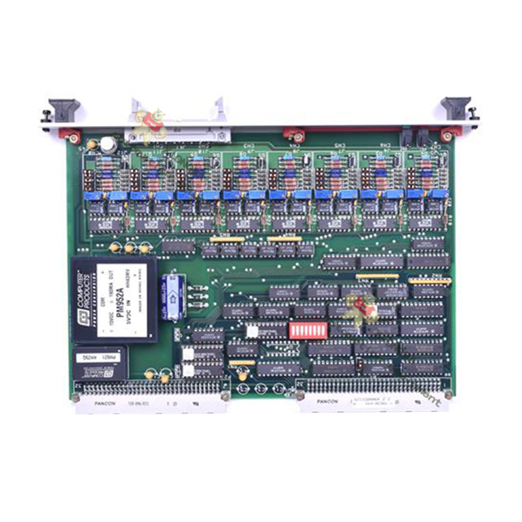
Two types of expansion modules are offered. 

Type B modules have industry standard PC/104 mechanical dimensions of 3.550″ x 3.775″. Each Type B module requires a separate Xycom front panel kit . Type A modules are 4.010″ x 5.091″ and are functionally the same as Type B modules but have an integral front panel. 

Type A modules do not require a front panel kit.

ARRIER CARD INSTALLATION

The carrier card requires the user to jumper the carrier card and attach it to the XVME PC/AT after

mounting the expansion modules. Section 1.2.1 contains information on the carrier card jumper

configuration for /1 and /12.

WARNING

All Xycom VME PC/AT CPU modules with functional revision levels of 4.1 or higher (functional revision levels and part numbers are located on a label on the P1 connector) feature a 16-bit compatible PC/104 expansion site.

This PC/104 expansion site requires a new version of the XVME-956 Modular I/O Carrier Module. If the CPU module’s functional revision level is 4.1 or higher, use the XVME-956/12 (part number 70956-012). If the functional revision level is less than 4.1, use the XVME-956/2 (part number

70956-002). Do not use the XVME-956/2 on a CPU module with functional revision levels of 4.1 or higher as this may cause damage to both modules.

VME-956/1/12 Carrier Card Jumpering

Both the 956/1 and 956/12 need to be jumpered. All AT signals except the data lines are buffered.

Signals which are outputs from the CPU are buffered and driven directly to the input pins of the I/O expansion module sites; such as the address bus, and the control signals. Signals which are outputs

from the I/O expansion module sites, are buffered and are connected to the CPU through jumpers; such as the IRQ signals, and the DRQ signals ttaching the XVME-956/1 to the XVME-PC/AT

The installation procedure involves three basic steps:

• installing the expansion module onto the XVME-956 (see Section 1.3)

• connecting the XVME-956 VME carrier card to the XVME-684, -686, and -687 modules via P1 and P2 of the VME backplane, and installing the XVME-956 and CPU into the VMEbus rack

• installing the printed circuit board (Inter-board connector) on the VMEbus backplane at J2, connecting the XVME-684 or XVME-686 and the XVME-956/1

1.2.2.1 Connect ing the XVME-956 Carrier Card to the XVME-PC/AT and Installing these

Cards in the VMEbus Rack

Xycom modules are designed to comply with all physical and electrical VMEbus backplane

specifications. The XVME-956/1 VME carrier card is a double-high, single-wide module and requires

one slot next to the XVME-684, -686, or -687 with both P1 and P2 connections.

Once the jumper and switch configurations for the XVME-956 are checked, and the expansion module is installed as indicated in Section 1.4, connect the XVME-956/1 VME carrier card to the XVME-684,-686 or -687 processor CPU module.

Procedure

1. Disconnect all power sources.

2.If the XVME-684, -686, or -687 module is currently installed in the VME backplane, remove

the processor module by gently pulling on it until it slides out of the chassis.

3. Place the XVME-956 board on top of the XVME-684 Xycom I/O module so that the P3 connectors line up.

4. Inser t the P3 pins of the XVME-956 VME card into the P3 socket of the XVME-684, -686, or -687 connecting module and press the two boards together.

The second step is sliding the connected cards into the VME backplane.

5. Make sure one card cage slot to the right of the Xycom XVME-684, -686 or -687 board set is clear and accessible.

6. Center the attached XVME-956 and XVME-684, -686 or -687 boards on the plastic guides in the slots.

7. Push the modules slowly to the rear of the chassis until the P1 and P2 connectors engage.

8. App l y straightforward pressure to the handles on the front of the panels until the connectors are fully engaged and properly seated. 

Do not use excessive force to engage the connectors.

Installing the Inter-Board Connector

All versions of the XVME-684, -686, and -687 modules route the PC/XT signals to rows A and C on the VMEbus P2 backplane. Because rows A and C are not bussed on a standard VMEbus P2 backplane, an inter-board connector is installed to pass the PC/XT signals from the first to the adjacent slot. 

The XVME-686 does not require this inter-board connector, and there will not be one installed on the XVME-686 system unless the application already uses an XVME-956 or an XVME-951. 

​With the addition of the XVME-956, this inter-board needs to be removed and replaced with a three-position inter-board connector (XVME-686 and -956 only needs a two-position).

All AT signals from the XVME-684, -686, and -687 are received through rows A and C of the XVME 956 connector P2, and from the inter-board connector P3. A three-position inter-board connctor will be used to connect the XVME PC/AT to the XVME-956 module. If the XVME-686 module is being used, ensure that rows A and C on P2, in the third slot, are not being used by another VMEbus card or contact the factory to exchange the three position inter-board connector for a two position inter-board connector. (The three position inter-board connector is included with the XVME-956 module). 

XYCOM Pro-Face 3712 KPM Industrial PCs

The 3712KPM units utilize a bright TFT 12.1″LCD flat panel display. 

Complex operations and screens can be displayed with clarity.

SVGA (800 x 600) resolution is recom mended.  

However, the 3712KPM units will display XGA (1024 x 768) resolution with some clarity degradation. The AGP graphics defaults to 4MB video RAM and will automati cally share RAM (up to 32 MB) with the system to allow full 32-bit color depth.

Higher Performance

With up to 1.26 GHz Pentium ®  III processors available, the 3712KPM units can drive the most demanding applications. 

The 3712KPM units ship standard with a Pentium III 1 GHz with 256K cache running at 133 MHz bus. A 1.26 GHz Pentium ®  III with 512K cache running at 133 MHz bus is an available option

Cutout Compatibility

The 3712KPM is directly cutout-compatible with many Xycom Automation legacy units. 

It offers a hardware upgrade path for many units, including the 2050, 8450, 9450, 9475,

9485, 9486, 9486 and the 9487 without the need to alter your current enclosure and/or

machine. 

For a more complete list, or to verify compatibility, contact Xycom Customer

Care.

Fits Your Needs

The 3712KPM can be configured many different ways. 

With four available expan sion slots (three full-length ISA/PCI, one ½ length PCI), many cost-effective, industry standard options are easily integrated. 

The optional dual hard drive, solid-state drive,externally accessible CompactFlash ™,  or

External Drive bay connector provide the storage solution you require. 

Additionally, the CD-ROM can be upgraded to CD-R/W, DVD,or DVD-R/W, so that even more storage and/or backup options are available. 

The optional 9000-XBAY allows you to externally mount any two IDE devices without requiring a

power supply or unreliable cabling.

Meets High Standards

To survive on the plant floor, the 3712KPM units meet NEMA 4/4x/12, IP65, FCC, UL,

CSA, and European CE mark requirements for industrial automation equipment. Xycom

Automation leads the industry in reliability,service, and support with an optional five

year warranty available.

Product Overview

The Xycom 3712KPM industrial computer is a high-performance computing device designed specifically for harsh industrial environments. With its robust and durable design, powerful computing capabilities, and excellent compatibility, it plays a key role in automation production lines, smart factories, energy monitoring, and other fields, providing stable and reliable hardware support and data processing platforms for industrial control systems.

Specification parameters

(1) Hardware configuration

Processor: Equipped with a high-performance industrial grade processor (specific model depends on version), it has powerful data processing and multitasking capabilities, can quickly respond to industrial control instructions, and ensure efficient system operation.

Memory: Supports large capacity memory expansion to meet the needs of complex industrial applications for data storage and fast read and write, ensuring smooth running of multiple programs simultaneously.

Storage: Equipped with high-speed solid state drives (SSDs), it has the characteristics of fast data read and write speed, strong shock resistance, and low energy consumption. At the same time, it supports multiple storage interfaces for convenient data storage and backup.

(2) Electrical parameters

Working voltage: Supports wide voltage input, can adapt to AC voltage range of 100-240V, frequency of 50/60Hz, effectively resists voltage fluctuations, and ensures stable operation in different power environments.

Power consumption: Optimized power management design reduces device operating power consumption, reduces energy consumption and heat dissipation burden, and improves overall operational efficiency.

(3) Physical specifications

Size and weight: Compact and sturdy design, reasonable size for easy installation in limited spaces such as industrial control cabinets and workstations, moderate weight, and balance portability and stability.

Protection level: It has a high protection level (such as IP65), is dustproof and waterproof, and can effectively resist the erosion of dust, oil, and water vapor in industrial environments, adapting to harsh production environments.

Heat dissipation design: adopting efficient heat dissipation structure, such as large-area heat dissipation fins combined with intelligent fan speed control system, to ensure that core components such as processors maintain reasonable working temperature under long-term high load operation and improve equipment reliability.

Core functions

(1) Industrial grade stability

After rigorous industrial testing and certification, it can operate stably in extreme temperature environments ranging from -40 ℃ to 85 ℃, and has excellent anti vibration and anti impact performance, effectively responding to frequent mechanical vibrations and transportation bumps in industrial sites.

Supports 24/7 uninterrupted operation, with hardware watchdog function that automatically restarts in case of system abnormalities, ensuring continuous and stable operation of industrial control systems, reducing downtime and production losses.

(2) Powerful communication and expansion capabilities

Rich interfaces: equipped with multiple standard communication interfaces, including Ethernet interface (supporting high-speed network communication, realizing fast data transmission and remote monitoring between devices), serial port (RS232/RS485, adapted to traditional industrial equipment communication), USB interface (convenient for connecting external storage devices, printers, etc.), CAN bus interface (suitable for industrial fieldbus communication, realizing real-time data exchange between devices), etc., to meet the connection needs of different industrial equipment.

Expansion slot: Provides PCI, PCIe and other expansion slots, which can flexibly expand functional modules according to actual application needs, such as adding data acquisition cards to achieve multi-channel analog/digital acquisition, or inserting video acquisition cards to achieve industrial field video monitoring functions.

(3) Intelligent management and control

Support remote management function, which enables remote device monitoring, configuration, upgrading, and fault diagnosis through the network, facilitating technical personnel to maintain and manage devices in different locations, reducing operation and maintenance costs and time costs.

Built in industrial grade real-time operating systems (such as Windows Embedded, Linux Industrial, etc.), with features such as fast startup, high real-time performance, and strong stability, can accurately control and process real-time data in industrial production processes.

XYCOM XVME-400 70400-001 card

Overview

The Xycom Automation XVME-400 and XVME-401Quad Serial I/O Modules are single-high, single-wide VMEbus modules that provide a VMEbus system with four serial communication channels.  

The XVME-400 and XVME-401 differ only in their communication interface:  the XVME-400 provides four RS-232C serial ports, while the XVME-401 provides four RS-422A/RS-485 serial ports.

Both modules contain two Z8530 Serial Communica tion Controller (SCC) chips which provide a variety of communication modes, including asynchronous, byte synchronous, and bit-oriented protocols. 

Each channel is independently programmable and has its own baud rate generator and modem signal controls.

The VMEbus interface directly maps the Z8530 SCC chips into the short I/O address space, starting on a jumper-selected 1 Kbyte boundary. 

The modules can also be jumpered to generate an interrupt on any of the seven VMEbus interrupt levels.  

The two Z8530 SCC chips can generate a total of 16 different interrupt vectors.

For applications not allowing I/O to be routed out the front panel, the XVME-490 and XVME-491 offer the same functionality as the XVME-400 and XVME-401.

In a 6U form factor, the I/O is routed via the VMEbus P2 connector on the back of the board

Product Overview

XYCOM XVME-400 70400-001 card is a powerful VME bus single board computer that integrates high-performance processors and rich interface resources. It can operate stably in complex industrial environments and provide reliable computing and control capabilities for automation control systems. With its excellent performance and reliability, it has been widely used in industrial automation production lines, aerospace testing equipment, and national defense and military equipment.

Specification parameters

Processor: Typically equipped with high-performance processors (specific models vary by version), capable of quickly processing complex computing tasks and real-time control instructions, ensuring efficient system operation.

Memory: A memory with a certain capacity that supports fast storage and reading of data, meeting the requirements of different application scenarios for data processing speed and storage capacity.

Storage: Supports multiple storage methods, such as flash memory, which can be used to store operating systems, applications, and important data.

Interface: Provides rich interfaces, including serial ports, network ports, USB interfaces, etc., to facilitate communication and data exchange with external devices, achieving flexible expansion and integration of the system.

Electrical parameters: The working voltage and other electrical parameters comply with industrial standards and can work stably in different power environments, with good electrical compatibility.

Physical specifications: Designed according to the VME bus standard size, it is easy to install in various VME chassis and has good mechanical compatibility and interchangeability.

Core functions

Data processing: The powerful processor and memory configuration enable it to quickly process large amounts of data, efficiently completing both real-time data collection and complex computing tasks, providing accurate data support for control systems.

Real time control: With real-time operating system support, it can achieve precise real-time control of external devices, ensure the stability and accuracy of industrial production processes, and is widely used for precise control of automated production lines.

Communication capability: Rich interfaces enable it to communicate with various devices, support multiple communication protocols, achieve data exchange and collaborative work with different systems, and facilitate the construction of complex industrial automation networks.

System Expansion: Through various interfaces and bus expansion capabilities, other functional modules can be easily added, such as analog input/output modules, digital input/output modules, etc., to meet the personalized needs of different application scenarios.

Working principle: The XVME-400 70400-001 card communicates data and interacts with other modules through the VME bus. During operation, the processor reads operating system and application instructions from memory, processes and analyzes input data, and then sends control instructions or output data to external devices through corresponding interfaces based on the processing results. At the same time, it can also receive data feedback from external devices, achieving bidirectional data transmission and closed-loop control of the system.

Precautions

Installation environment: It should be installed in a dry, well ventilated, and suitable temperature environment, avoiding high temperature, high humidity, dust, and strong electromagnetic interference to ensure the normal operation and service life of the equipment.

Installation operation: During the installation and disassembly process, it is necessary to ensure that the equipment is powered off and take anti-static measures to avoid damage to the circuit board caused by static electricity. Ensure that all interfaces are securely connected during installation to avoid communication failures caused by looseness.

Power requirements: Use a stable power supply that meets the equipment requirements to avoid damage to the equipment caused by excessive power fluctuations or abnormal voltage. Before connecting the power supply, carefully check whether the power parameters match the equipment specifications.

Software maintenance: Regularly update the operating system and applications, fix potential vulnerabilities, and improve system stability and security. At the same time, regularly backup important data to prevent data loss.

XYCOM模块VME总线XVME-400(2024全+境/派+送/直+达)_技术研讨_仪器仪表技术文献_阿仪网

Xycom 3515 KPM PM101906 Operator Interface

Product Overview

The 3500 series of flat panel industrial PCs with 6-slot ISA/PCI expansion include the 3515, 3515KPM, and 3512KPM models.

These industrial PCs offer a powerful, compact package for the factory floor and other harsh environments.

The 3515 is an industrial PC with a display only (touchscreen optional).

The 3512KPM and 3515KPM is an industrial PC with a display, integrated keypads, and an integrated mouse.

They feature an open architecture to meet a wide variety of applications that require both a powerful PC and a durable industrial front panel.

The PCs integrate a computer card cage, mass storage, display, and power supply in a truly industrial form.

Their modular design allows easy access to expansion boards, jumpers, power supply, flat panel dis

play, and disk drives.

The front panel of every model is sealed to NEMA 4/4X/12, and the flat panel display is protected by an impact-resistant shield

Standard Features

With AHIP6+ board

Pentium® II technology

PCI 64 bit video controller, 2 MB video RAM

PCI local-bus IDE controller

Two 168-pin SDRAM DIMMs that support 32, 64, 128, and 256 MB options

Two USB ports

100MHz front side bus with Pentium II processors

With AHIP370+ board

Celeron ® technology

AGP 64 bit video controller, 2 MB video RAM

PCI local-bus IDE controller

Two 168-pin SDRAM DIMMs that support 32, 64, 128, and 256 MB options

Two USB ports

On all units

Two serial COM ports

RS-232

RS-232 or RS-485

Flat panel display

15-inch flat panel, 1024×768 resolution (3515 and 3515KPM)

12.1-inch flat panel, 800×600 resolution (3512KPM)

Parallel port

VGA port

Flash BIOS

9-inch mounting depth

3.5-inch internal, side access floppy drive

Six AT-bus full-length expansion slots

Four ISA slots

One ISA or PCI slot

One PCI (4.8” maximum length with AHIP6+ board)

IR Port (IrDA and ASKIR compatible)

Rear PS/2 keyboard port and AUX port (also a front PS/2 keyboard port on 3512KPM and 3515KPM)

Status LEDs

Power

Disk

Com

Input

3.5-inch internal IDE  hard drive

MS-DOS®

Front panel sealed to meet NEMA 4/4X/12 specifications when panel mounted in a

suitable fire and electrical enclosure.

Approved for use in Class I, Division 2 hazardous locations

Autosensing AC power supply

Side power connector with retainer bracket

Optional Features

Touchscreen resistive technology with less than 1.5% linearity error

Higher capacity IDE hard drives and solid state drives

3512KPM

40 relegendable function keys (80 with the F/A function)

Numeric, PC control, and alpha keypads

Integrated mouse

3515KPM

40 relegendable function keys (80 with the F/A function)

Numeric, PC control, and alpha keypads

Windows start menu and pop-up menu keys

Integrated mouse

Flat-panel display

15.0-inch TFT flat panel (3515 and 3515KPM)

12.1-inch TFT flat panel (3512KPM)

CD-ROM (internal)

Pre-installed PCI 10/100 Base-T Ethernet card

External floppy drive 9000-EXF

Front mount floppy kit 9000-FFK

Front access panel for floppy port and keyboard port 9000-FKA

Preloaded Microsoft Windows 95 or Windows NT® operating system

Product Overview

Xycom 3515 KPM PM101906 is an operator interface designed specifically for industrial environments, aimed at providing efficient and convenient human-machine interaction solutions for various automation systems. This interface has been widely used in the field of industrial automation due to its reliable performance, rich functionality, and good compatibility.

Specification parameters

Display specifications: Equipped with a 15 inch display screen, it can clearly present various information and meet the data visualization needs of industrial sites. Whether it is monitoring complex process flows or displaying equipment operating parameters, it can provide intuitive and accurate visual feedback for operators.

Electrical parameters: The working voltage supports 115V AC or 230V AC, with a frequency of 50/60Hz, suitable for power supply standards in different regions. The rated current is 6.3A, ensuring stable operation under normal working load and providing power guarantee for the continuous and reliable operation of the equipment.

Physical specifications: The overall design is compact, with optimized dimensions and weight, making it easy to install on various industrial control cabinets or workstations. Its sturdy shell material has certain protective properties, which can resist interference such as dust and vibration in industrial environments, ensuring the normal operation of the equipment under harsh conditions.

Core functions

Convenient operation: With a concise and clear interface, operators can get started without complex training. Through an intuitive graphical interface and convenient operation buttons, it is possible to quickly start, stop, and adjust parameters of the automation system, thereby improving work efficiency.

Data Interaction: Supports data communication with various industrial equipment and control systems, enabling real-time acquisition of equipment operating status, process parameters, and other information, and accurately transmitting operator instructions to the corresponding equipment. This efficient data exchange capability makes the entire automated production process more coordinated and smooth.

Status monitoring: Real time monitoring of the operating status of various devices in the automation system, visually displaying the normal, fault, alarm, and other status of the devices through different colors, icons, and other methods. Once the equipment encounters an abnormality, it can promptly issue an alarm to remind operators to handle it, effectively reducing equipment downtime and ensuring production continuity.

Working principle

Xycom 3515 KPM PM101906 establishes a connection with external automation systems through internal communication modules. When the system is running, the interface continuously receives real-time data from the device and parses it to display it in an intuitive form on the screen. At the same time, the operator’s operation instructions on the interface will be quickly captured and encoded before being transmitted to the corresponding equipment or control system, thereby achieving effective control over the entire automation process.

​Precautions

Installation environment: It should be installed in a dry and well ventilated environment, avoiding direct sunlight and high temperature and humidity. Stay away from strong electromagnetic interference sources to prevent any impact on the normal operation of the interface.

Power connection: Ensure that the power connection is correct and stable, and avoid damage to the equipment caused by power fluctuations or abnormal voltage. Before connecting the power supply, it is necessary to carefully check whether the power parameters match the equipment requirements.

Daily maintenance: Regularly clean the display screen to keep it clear, so that operators can accurately read information. Regularly check the connection lines of the equipment to ensure that they are firmly connected and free from looseness, damage, and other issues.

REFURBISHED XYCOM 3612KPM PROFACE OPERATOR INTERFACE 1000-256-CDF-2K ...

Xycom AOUT XVME-530 P/N 70530-001 FREV 2.2L

Basic information

Product model: XVME-530

Part number: 70530-001

Version: FREV 2.2L

Bus standard: VME bus, compliant with VITA 1.1 standard, ensuring compatibility and interoperability with other VME devices.

Output channel

Number of channels: 16 analog output channels, capable of controlling multiple devices or actuators simultaneously.

Output type: voltage output or current output, users can choose through software or hardware configuration.

Electrical characteristics

Voltage output range: Multiple options including ± 10V, 0-10V, ± 5V, 0-5V, etc., to meet the needs of different application scenarios.

Current output range: 4-20mA, 0-20mA, suitable for long-distance transmission and situations with high requirements for driving load capacity.

Resolution: 12 bits, capable of providing high output accuracy to ensure control accuracy.

Establishment time: The typical value is 25 μ s to ensure rapid response to system output changes.

Output accuracy: At room temperature (25 ℃), the voltage output accuracy is ± 0.1% FSR (full range), and the current output accuracy is ± 0.2% FSR; Within the working temperature range (-40 ℃ -+85 ℃), the voltage output accuracy is ± 0.3% FSR, and the current output accuracy is ± 0.5% FSR.

Interface and Communication

Interface type: DB37 connector, used to connect external devices and sensors.

Communication protocol: Communicate with the host through the VME bus, support standard VME data transmission protocol, and achieve fast data exchange.

Work environment

Working temperature: -40 ℃ -+85 ℃, able to adapt to harsh industrial environments.

Storage temperature: -55 ℃ -+125 ℃.

Humidity: 5% -95% (no condensation), ensuring normal operation in humid environments.

Power requirements

Working voltage:+5V DC, typical current consumption is 350mA;+15V DC, typical current consumption is 35mA; -15V DC, typical current consumption is 30mA.

mechanical properties

Size: Complies with the VME 6U standard size, making it easy to install in a VME chassis.

Weight: Approximately 500 grams (subject to actual product).

Core functions

Multi channel independent output

16 analog output channels can be independently configured as voltage or current output modes, supporting mixed use of different signal ranges, suitable for collaborative control of multiple actuators in complex industrial control systems.

Dynamic output update

Supports single channel or multi-channel synchronous updates, and can quickly refresh output values through the VME bus to meet real-time control requirements. For example, in robot motion control, synchronous motion control of multiple joints can be achieved.

Output protection mechanism

Short circuit protection: automatically limits the current when the output terminal is short circuited to prevent module damage

Overvoltage protection: Built in limiting circuit to prevent output voltage from exceeding the safe range

Thermal shutdown protection: automatically shuts off the output when the temperature exceeds the threshold, and automatically restarts after the temperature is restored

Fault diagnosis function

Output status monitoring: Real time detection of whether the output of each channel is normal

Sensor disconnection detection: supports detecting the connection status of external loads

Fault code storage: Record recent fault information for easy maintenance

Working principle

The XVME-530 module is based on digital to analog conversion (DAC) technology to achieve signal conversion. The workflow is as follows:

Data reception: Receive digital control signals (12 bit binary values) sent by the host through the VME bus

Data cache: The received data is temporarily stored in registers inside the module

DAC conversion: Digital signals are converted into analog voltage/current signals through high-precision DAC converters

Signal conditioning: The converted analog signal is processed by amplification, filtering, and other conditioning circuits to ensure the stability and accuracy of the output signal

Output driver: The conditioned signal is transmitted to the external load through the output driver circuit

The module adopts optoelectronic isolation technology internally to achieve isolation between digital circuits and analog circuits, effectively suppressing electromagnetic interference, improving anti-interference ability and system reliability.

Precautions

Installation and wiring

It needs to be installed in a metal chassis that meets EMC standards, ensuring good grounding

Analog signal lines should be wired separately from digital signal lines to avoid cross interference

Suggest using shielded cables to connect external devices, with the shielding layer grounded at one end

Power requirements

The power supply needs to be stable, and the ripple coefficient should be less than 50mV

Each power pin should be connected according to regulations to avoid reverse connection or short circuit

It is recommended to use an independent power supply to power the module and avoid sharing power with high load devices

Configuration and Programming

Before first use, it is necessary to initialize and configure the output mode, range, and other parameters through software

When programming, attention should be paid to the correctness of data format and register addresses

Avoid frequent reading and writing of module registers to prevent data conflicts

Environmental adaptability

Avoid using in environments with strong magnetic or electric fields

The working environment should be well ventilated to avoid dust accumulation

When used in high humidity environments, moisture-proof measures should be taken

XYCOM XVME-530 Isolated Analog Output Module-Xiongba Automation

Xycom XVME-100 RAM Memory Module

​Storage capacity and technology type

Capacity specifications

XVME-100 typically offers multiple storage capacity options, commonly including 32MB, 64MB, 128MB, etc., to meet the data storage requirements of different application scenarios. For example, in industrial automation control systems, if there is a large amount of real-time data caching and processing involved, the larger 128MB specification can ensure efficient system operation and avoid data loss or processing delays caused by insufficient memory.

Technical type

This module adopts dynamic random access memory (DRAM) technology, which has the characteristics of high cost-effectiveness and fast read and write speed. It can quickly respond to the system’s read and write requests for data, ensuring the smooth operation of the computer system. In some industrial control scenarios that require high real-time performance, such as real-time monitoring and control of automated production lines, DRAM technology can process sensor data in a timely manner, enabling the control system to respond quickly.

Electrical characteristics

Working voltage

The working voltage of XVME-100 is generally 5V DC (direct current), which is a common voltage value that meets industrial standards and is easy to adapt to the power supply system of other industrial equipment, ensuring stable power supply in industrial environments. In complex electrical environments such as factory workshops, a stable 5V power supply can ensure the normal operation of memory modules and reduce the risk of faults caused by voltage fluctuations.

Power consumption

The power consumption of this memory module is relatively low, taking the 128MB specification as an example, the typical power consumption is about 2-3W. The low-power characteristic not only helps to reduce the energy consumption of the entire system, but also reduces heat generation and improves the stability of the device during long-term operation, especially suitable for applications such as industrial control cabinets with limited heat dissipation conditions.

Interface and Physical Characteristics

Interface type

XVME-100 adopts the VME (Versa Module Eurocard) bus interface, which has advantages such as high reliability and high-speed data transmission capability. The VME interface supports multi master device operation, with a data transmission rate of up to 40MB/s, which can meet the demand for fast transmission of large amounts of data in industrial automation systems. For example, in industrial data acquisition systems, the collected data can be quickly transmitted to the processor for processing.

Physical dimensions

The module size follows the 6U specification of the VME standard, which is 340mm long and 233.35mm wide. This standardized size design makes it easy to install on various chassis or backboards that comply with the VME standard, with good universality and interchangeability, making it convenient for system integrators to build and maintain the system.

Weight

The weight of XVME-100 is relatively light, approximately between 200-300 grams, with slight differences in specific weight due to capacity and internal component configuration. The lighter weight makes the operation more convenient during equipment installation and maintenance, reducing the load-bearing pressure on the equipment installation structure.

Performance parameters

Read and write speed

Its read speed is usually between 10-20ns (nanoseconds), and the write speed is about 15-25s. Fast read and write speeds are crucial for applications that require frequent access to data, such as in industrial real-time database systems, where new data can be quickly written into memory and historical data can be quickly read for analysis, providing timely and accurate data support for industrial decision-making.

Data transmission rate

With the help of the VME bus interface, the data transmission rate of XVME-100 can reach 40MB/s, enabling high-speed data exchange with other devices in the system (such as processors, storage devices, etc.), ensuring the data processing efficiency of the entire industrial system. In the control system of industrial automation production lines, high-speed data transmission enables the controller to quickly obtain sensor data and issue control instructions in a timely manner, ensuring the efficient operation of the production line.

Environmental adaptability

Working temperature range

XVME-100 can operate within a wide temperature range, typically from -40 ° C to+85 ° C. This allows it to adapt to various harsh industrial environments, whether in cold northern industrial sites or hot southern factory workshops, ensuring stable operation of industrial systems without being affected by environmental temperature.

Humidity range

This memory module can operate normally in an environment with a relative humidity of 5% -95% (without condensation). In some industrial scenarios with high humidity, such as textile factories, food processing plants, etc., it can effectively avoid circuit short circuits or data errors caused by humidity issues, ensuring the reliability of the system.

Seismic resistance

XVME-100 has excellent seismic design and can withstand a certain degree of mechanical vibration and impact. In industrial environments, equipment may be affected by vibrations caused by machine operation, transportation, etc. This module ensures the stability and integrity of data storage in vibration environments through optimized mechanical structures and component fixing methods.

GE SR489-P5-LO-A20-E relay protection

Core technical parameters and functional characteristics

Protection function system

Stator and rotor protection: integrated stator grounding protection (100% stator grounding monitoring), stator thermal overload protection (combined with RTD temperature sensor and current model), negative sequence overcurrent protection (rotor thermal stress monitoring), and excitation fault protection.

Bearing and vibration monitoring: 12 RTD inputs support bearing temperature monitoring, and 4 analog inputs can be connected to vibration sensors to achieve bearing overheating and mechanical vibration warning.

Power and frequency protection: Supports overvoltage/undervoltage, overclocking/underfrequency, reverse power (to prevent motor operation), and demagnetization protection, suitable for 25Hz, 50Hz, or 60Hz power grid environments.

Measurement and communication capabilities

Multi dimensional data collection: Real time monitoring of parameters such as current, voltage, power, frequency, power factor, etc., supporting energy metering and event recording (256 time scale events).

Flexible communication interface: standard RS232/RS485 port (Modbus RTU protocol), optional Ethernet (Modbus TCP/IP), supports integration with SCADA/DCS systems.

Human computer interaction interface: The 40 character LCD screen supports local parameter configuration, fault diagnosis, and waveform playback (128 cycle waveform capture).

Hardware and environmental adaptability

Input/output configuration: 9 digital inputs, 6 output relays (including trip/alarm contacts), 4 programmable analog outputs (4-20mA), which can directly drive PLC or external controllers.

Power compatibility: The control power supply supports 20-60V DC or 20-48V AC (48-62Hz), adapting to various power supply conditions in industrial sites.

Environmental reliability: Operating temperature range of -40 ° C to+60 ° C, protection level IP20 (dustproof), meeting the long-term operational needs of industrial environments.

Application scenarios and industry value

Power generation and energy sector

Small and medium-sized generator protection: widely used in industrial self owned power plants, distributed energy stations, and renewable energy projects, such as grid protection for gas turbines and wind turbines.

Cogeneration system: supports reverse power protection and automatic synchronization control to ensure the stability of the unit during grid switching.

industrial process control

Redundancy protection for key equipment: In scenarios such as petrochemicals and mines, it provides backup protection for compressors and pumps driven by high-voltage motors to prevent production interruptions caused by generator failures.

Mechanical condition monitoring: Predictive maintenance is achieved through the integration of vibration sensors, such as early warning of bearing wear or rotor imbalance.

Power grid connection and stability

Isolation operation protection: In microgrids or off grid systems, frequency/voltage protection is used to prevent islanding effects and ensure system stability.

Harmonic suppression: The negative sequence current monitoring function can identify harmonic pollution in the power grid and avoid generator overheating and damage.

Technological Evolution and Alternative Solutions

Alternative model Multilin 889

Function upgrade: As the successor product of SR489, Multilin 889 adds sub cycle differential protection, IEC 61850 communication, and Wi Fi configuration functions, supporting more complex generator transformer protection.

Compatibility design: GE provides a dedicated upgrade kit that can directly replace SR489, retaining the original wiring terminals and communication protocols to reduce renovation costs.

Digitization and Intelligence

Network Security Enhancement: The Multilin 889 supports AAA authentication, Radius, and Syslog, meeting power grid security standards such as NERC CIP.

Edge computing capability: built-in programmable logic controller (PLC) can realize localized logic control and reduce dependence on the central control system.

Industry standards and certifications

Compliance: Compliant with international standards such as IEC 60255-1 and IEC 61850 (Multilin 889), and certified for industrial environments by organizations such as DNV GL.

Quality Assurance: GE provides a 10-year warranty (Multilin 889) and meets IPC-A-610E Class 3 electronic manufacturing standards to ensure long-term reliability.

Key points of operation and maintenance

Installation and debugging

Drawer style design: Supports live plugging and unplugging, making it easy to quickly replace modules during maintenance and reducing downtime.

Waveform simulation test: Built in waveform simulation function can verify the correctness of protection logic and reduce the difficulty of on-site debugging.

fault diagnosis

Event recording and analysis: Export event logs and waveform data through RS232 interface, and use GE’s PowerTools software for fault tracing.

Environmental monitoring: Some models support environmental temperature and humidity monitoring, which can provide early warning of equipment aging caused by dust or humidity.

precautions

Discontinuation and replacement suggestions

SR489-P5-LO-A20-E has been discontinued. It is recommended that the new project directly adopt Multilin 889. Technical support for upgrading the existing system can be obtained through GE authorized channels.

Compatibility verification

If integration with existing systems is required, it is necessary to confirm the compatibility of communication protocols and, if necessary, achieve protocol conversion through a Modbus gateway.

summarize

GE SR489-P5-LO-A20-E has become a classic solution for protecting small and medium-sized generators due to its comprehensive protection functions, flexible communication capabilities, and industrial grade reliability. Although discontinued, its replacement model Multilin 889 has achieved significant improvements in intelligence, network security, and digital integration. For Chinese users, the local supply chain and technical support network can effectively ensure equipment operation and maintenance, and the localization adaptation case of Multilin 889 further reduces the upgrade threshold. It is recommended that users choose appropriate solutions based on their specific needs and prioritize the long-term benefits brought by technological evolution.

GE SR489-P5-LO-A20-E Generator management relay Quality assurance ...

KONGSBERG DPS132 positioning system host navigation ship

Technical principles and functional characteristics

High precision positioning mechanism

DPS132 is based on dual frequency GPS signals (L1 and L2 frequency bands), combined with satellite based augmentation systems (SBAS, such as WAAS, EGNOS) and wide area differential correction technology, which can improve positioning accuracy to sub meter level. The system has a built-in lever arm compensation function, which can accurately calculate the positions of multiple measurement points on the ship by integrating the ship’s heading information, meeting the needs of multi-sensor fusion.

Redundancy Design and Reliability

The system adopts a two-level redundant control architecture with a fail safe mechanism, which can automatically switch to backup modules when critical components fail, ensuring the continuity of positioning function. Its hardware design meets the high reliability requirements of maritime environments, supports Windows NT4.0 operating system, and has long-term stable operation capability.

Multi mode operation capability

DPS mode: By processing real-time data from sensors such as GPS, gyro compass, sonar, etc., the thruster thrust is dynamically adjusted to counteract external forces such as wind, waves, and currents, enabling the ship to hover at a fixed point or navigate along a preset path.

Navigation mode: Used as a conventional navigation system, it provides basic position, speed, and heading information.

Data visualization and user interface

DPS132 can be integrated with KONGSBERG’s K-Master comprehensive bridge system, displaying ship status, sensor data, and environmental parameters through a unified graphical interface (such as touch screen), and supporting linkage control with ECDIS, radar, autopilot, and other equipment.

Application scenarios and industry value

Marine engineering operations

In tasks such as deepwater drilling and submarine cable laying, DPS332 can ensure that ships maintain a stable position without anchoring conditions, such as controlling system errors within 0.3 meters in Class II sea conditions. Its precise positioning ability significantly improves operational efficiency and reduces the time and cost consumption of traditional anchoring methods.

Scientific expedition and deep-sea exploration

Research vessels such as the “Exploration 2” are equipped with a DP2 level dynamic positioning system (similar to DPS132 technology), which can support the deployment and recovery of manned submersibles and precise operation of deep-sea observation equipment in complex sea conditions. The low noise characteristics of DPS332 (electric propulsion design) can also provide a stable working environment for underwater acoustic equipment and improve data acquisition quality.

Port and narrow water operations

The automatic tracking and heading control functions of DPS332 can assist crew members in dealing with complex steering and obstacle avoidance needs in entering and exiting ports or congested waterways, reducing human operational risks.

Industry standards and certifications

Although specific certification information was not explicitly mentioned in the search results, KONGSBERG, as a global maritime technology leader, typically meets the Dynamic Positioning (DP) standards of the International Maritime Organization (IMO) (such as DP-2 or DP-3) and has been certified by authoritative organizations such as DNV GL. For example, the DP2 level system of “Exploration 2” reflects the practical application of KONGSBERG technology in the field of scientific research ships.

Core technical parameters

positioning accuracy 

Horizontal accuracy: With the support of SBAS (Satellite Based Augmentation System), the typical value is * *<1 meter * * (RMS); Combined with wide area differential correction technology, it can be upgraded to sub meter level (0.3-0.5 meters).

Vertical accuracy: * *<2 meters * * in SBAS mode, and can be optimized to 1-1.5 meters in dual frequency GPS mode.

Dynamic response: The system delay is less than 100ms, meeting the real-time control requirements of the ship.

Navigation sensor compatibility

Support multi-sensor fusion: GPS (L1/L2 dual frequency), gyro compass, MRU (motion reference unit), sonar, etc.

Built in Lever Arm compensation function, which can access ship heading information and calculate the positions of multiple measurement points on board.

Differential correction support

Compatible with DGPS (Wide Area Differential), SBAS (such as WAAS, EGNOS), and UHF link differential (for offshore loading scenarios).

Physical and environmental parameters

​Hardware configuration

Host unit: 4U standard rack mounted design, weighing approximately 15-20kg (referring to similar maritime equipment).

Interface type:

Communication interface: RS-422/485, Ethernet (supporting NMEA 0183/2000 protocol).

Sensor interfaces: gyro compass (such as KONGSBERG HUGIN), MRU, sonar (such as HIPAP 500).

Power requirements:

Input: 220-240V AC, 50/60Hz, power consumption * * ≤ 500W * * (including redundant modules).

Backup power supply: Supports DC 24V (optional UPS).

Environmental adaptability

Working temperature: -20 ° C to+55 ° C (compliant with maritime equipment standards).

Humidity: 5% -95% RH (non condensing).

Protection level: IP54 (dustproof and splash proof), in compliance with DNV GL maritime environmental certification.

Redundancy and reliability

System Architecture

Secondary redundancy: Main/backup controllers, power modules, and communication links, with a fault switching time of less than 200ms.

Data backup: Supports local storage (SSD) and remote log transfer.

Certification standards

Complies with the IMO MSC.86 (70) dynamic positioning standard and supports DP-2/DP-3 level applications (such as the configuration of the “Haiyang Shiyou 981” drilling platform).

Certified by DNV GL (specific model confirmation required, reference to similar products).

function characteristics

Multi mode operation

DPS mode: Real time dynamic positioning, supporting fixed-point hovering, path tracking, and automatic obstacle avoidance.

Navigation mode: Basic navigation information output (latitude and longitude, speed, heading).

Test mode: Sensor calibration and system diagnosis.

data output

Output frequency: 10Hz (configurable).

Data format: NMEA 0183/2000, KONGSBERG specific protocol (such as K-Bridge).

Application scenario parameters

Marine engineering operations

Under the second level sea conditions (wind speed of 12-19 knots, wave height of 1.25-2.5 meters), the position maintenance error is * * ≤ 0.5 meters * *.

Support deepwater operations (water depth>3000 meters), compatible with HIPAP sonar positioning system.

Scientific expedition and deep-sea exploration

Low noise design (compatible with electric propulsion), supporting stable operation of underwater acoustic equipment.

Integrate K-Master bridge system to achieve multi device linkage control.

Scalability

Communication Expansion

Support UHF wireless links (used for relative positioning between ships, such as loading scenarios at sea).

Can be connected to KONGSBERG Intelligent Awareness system (AI assisted navigation).

software upgrading

Support remote firmware updates and feature extensions (such as adding sensor protocols).

Industry application examples

The “Haiyang Shiyou 981” drilling platform is equipped with DPS132 and DPS200 dual redundant positioning systems, which meet the DP-3 level requirements and have a positioning accuracy of less than 0.5 meters.

The “Exploration 2” scientific research vessel adopts similar DP2 technology, supporting the deployment of manned submersibles and the operation of deep-sea observation equipment.

PRO-FACE XYCOM 1546 Heavy Industrial PC

Product Overview

The 1546 and 1547 Node Box Industrial PCs offer a powerful, compact package for the factory floor and other harsh environments.

These node box industrial PCs feature an open architecture to meet a wide variety of applications that require both a powerful PC and a durable industrial enclosure.

The systems integrate a computer card cage, mass storage, and power supply in a truly industrial form.

The processor board combines all the functions of a complete PC/AT® compatible computer on a single industrially hardened circuit board.  

Standard Features  

The 1546 and 1547 units come standard with the following features:

AIM4 board

Wall or shelf mountable

Flash BIOS

SATA HD controller for up to 2 drives

Removable 40 GB SATA hard drive(s), rear access

AGP Video Controller, 4M of system DRAM, up to 32M

PCI local bus IDE controller (for CD/DVD and CF options)

Two 240 pin DDR2 DIMM sockets that support 256MB, 512MB, 1GB and 2GB options

Intel® Socket 478 Celeron® M or Pentium® M options up to 2.0GHz 400MHz or 533MHz front side bus depending on the processor type

1546 – Four AT bus expansion slots  

One PCI (8.0” max)

One PCI (9.0” max)

One ISA (9.0” max)

One PCI or ISA slot (9.0” max)

1547 – Four AT bus expansion slots  

One ½ length PCI

One full length PCI

One full length ISA

One full length PCI or ISA slot

IBM® PS/2® keyboard port and mouse port

Four serial COM ports, with three external ports configured as RS-232 and one configurable as either RS-232 or RS-422 or RS-485.

The fourth port is an internal header only and defaulted as disabled.

Parallel port  

VGA port

Four USB 2.0 ports

Legacy USB keyboard and mouse support

Legacy USB floppy, USB CDROM, and USB mass storage support

Two onboard Ethernet ports, one is a 10/100 BASE T and the other is 10/100/1000 BASE T

Microsoft Windows XP® operating system

Internal rear access Compact Flash (CF) interface

120/240 VAC 50/60Hz Auto switching power supply

UL Listed for use in Class I and Class II, Division 2 hazardous locations, Groups A, B, C, D, F, and G

Optional Features

Following are optional available features of the 1546 and 1547:

Higher capacity SATA hard drives and solid state drives  

Various CD/DVD drive options

Internal rear access floppy

Various processor speeds

Preinstalled Windows® 2000, or Windows XP® Professional

External 9000-USBF, USB floppy (requires Windows 2000, or XP)

CompactFlash™ options up to 4GB

2.5” Dual hard drives

2.5” RAID array support

24VDC power supply (on 1547 units only)

The figures and tables on the next several pages illustrate the internal and external components on the front and back panels of the unit to help you locate the features of the 1546 and 1547 Node Boxes.

Installation Overview

Warning

For installation in Hazardous Locations, review the Hazardous Locations

Installation section in this chapter before startup.  

The rugged design of the 1546 and 1547 Node Boxes allows it to be installed in most industrial environments.

The system is generally placed in a NEMA 4/4X/12 enclosure to protect against contaminants such as dust, and moisture.

Metal enclosures also help minimize the effects of electromagnetic radiation that nearby equipment can generate.

For Underwriters Laboratories (UL) compliance, the unit must be installed within a suitable fire enclosure.

Read the following sections carefully to be sure that you are complying with all the safety requirements.

Select a NEMA rated enclosure and place the unit to allow easy access to the system ports (see other sections in this chapter and Appendix A).

To assure a NEMA 4 seal choose an approved enclosure that has a 14-gauge(0.075 in/1.9 mm thick steel or 0.125 in/3.2 mm thick aluminum) front face.

Be sure to account for the unit’s depth when choosing the depth of the enclosure.

Create a mounting location in the enclosure (see System Mounting Dimensions).

Be sure to place the unit at a comfortable working level

Make sure the area around the mounting location is clean and free from metal burrs

Mount the unit position and properly secure the unit into the panel.

Tighten the fourteen #10 screws to 20 inch-pounds (2.597 Newton-meters /23Kgf cm).

Construct a power cable following the instructions in AC Power Cable in this chapter.

Attach one end of the power cord to the power receptacle on the unit and the other end to a properly grounded 115/230 VAC, 50-60 Hz outlet.

A ground path from the unit chassis to the enclosure chassis can be established using the 6-32 threaded ground point hole provided on the bottom panel of the unit

Turn on power to the system. The system will boot up the installed operating system.

Install the application software via a floppy drive, CD-ROM, or the network.

Additional aspects to take into account when mounting your 1546 and 1547 Node

​Boxes:

Consider locations of accessories such as AC power outlets and lighting (interior lighting and windows) for installation and maintenance convenience

Prevent condensation by installing a thermostat-controlled heater or air conditioner

To allow for maximum cooling, avoid obstructing the airflow 

Place any fans or blowers close to the heat generating devices.

If using a fan,make sure that outside air is not brought into the enclosure unless a fabric or other reliable filter is used. This filtration prevents conductive particles and other harmful contaminants from entering the enclosure.

Do not select a location near equipment that generates excessive electromagnetic interference (EMI) or radio frequency interface (RFI). Examples of these types of equipment are: high power welding machines; induction heating equipment; and large motor starters.

Pro-face Industrial PCs | Advantage Industrial Automation

Xycom XVME-660 processor module 70660-716

Xycom XVME-660 processor module 70660-716

Product positioning and technical specifications

Core functions:

Processor configuration: Using Intel Celeron 566MHz or Pentium III 600-700MHz processors (specific model to be confirmed according to version), supporting real-time operating systems (such as VRTX, UNIX) and industrial communication protocols.

VME bus compatibility: Supports 6U VME standard, providing high-speed data transmission capability, suitable for scenarios with high real-time requirements such as aerospace and semiconductor manufacturing.

Storage and Expansion:

Memory: Onboard 64MB SDRAM, supporting expansion up to 128MB (to be confirmed based on specific version).

Interface: Includes PMC (PCI Mezzanine Card) expansion slots, which can be connected to high-speed I/O modules or communication cards.

Technical parameters:

Working voltage: Typical value is+5V DC, supporting redundant power input.

Temperature range: Industrial grade design (-40 ° C to+85 ° C), suitable for harsh environments.

Communication protocol: Supports VME64x protocol, compatible with VMEbus standard, and can seamlessly integrate with other VME modules (such as XVME-202 I/O module).

System compatibility:

Physical dimensions: 70660-716 are 6U VME modules that need to be matched with 6U slots to avoid confusion with 3U modules.

Driver support: Some VME systems require additional configuration of drivers or firmware. It is recommended to request technical documentation from the supplier in advance.

Recommended alternative solutions:

Pro Face alternative solution: Pro Face does not directly provide a replacement product for 70660-716. AGP 3xxx series industrial PCs can be considered to be paired with extended I/O modules (such as ADAM-4000 series) to achieve similar functions.

Third party VME modules, such as Mercury Systems MVME 162-110 (32 channel DIO), are compatible with the VME64x protocol and support long-term spare parts supply.

Repair and maintenance recommendations

Fault diagnosis:

LED indicator light: Determine the fault through the status light on the module (such as a constant red light indicating processor abnormality).

Self diagnostic function: Some VME systems support remote diagnosis and can read module error codes (such as memory verification errors) through software.

Product Overview

The XYCOM XVME-660 processor module is a product that plays an important role in the field of industrial automation control. It is designed based on the VME (Versa Module Europa) bus architecture, providing stable and efficient core computing capabilities for industrial control systems. It is widely used in aerospace, semiconductor manufacturing, industrial automation production lines, and other scenarios that require high real-time and reliability.

Specification parameters

Processor performance: Using Intel Celeron 566MHz or Pentium III 600-700MHz processors, the specific model varies depending on the product version. This processor configuration can meet the requirements of complex data processing and real-time control operations in industrial scenarios.

Memory configuration: Onboard 64MB SDRAM memory, and some versions support expansion up to 128MB, sufficient memory can ensure the smoothness of the system when running complex programs and processing large amounts of data.

Physical dimensions: The VME module belongs to the 6U specification and can adapt to VME bus slots that comply with the 6U standard. It fits the internal structural design of industrial control cabinets and other equipment in terms of spatial layout.

Working voltage: The typical working voltage is+5V DC and supports redundant power input, which greatly improves the power supply stability of the equipment in industrial environments and reduces the risk of system shutdown due to power fluctuations or failures.

Temperature range: Designed as an industrial grade working temperature range, from -40 ° C to+85 ° C, it can adapt to various harsh industrial environments, whether in cold outdoor work scenarios or high-temperature industrial production workshops, and can operate stably.

Core functions

Data processing and computation: With its high-performance processor, it can quickly execute various industrial control algorithms, such as real-time analysis and processing of large amounts of data collected by sensors on production lines, providing accurate decision-making basis for control systems.

Real time control: XVME-660 can meet the strict requirements of industrial automation systems for real-time performance, and can quickly respond and execute control instructions for external devices, ensuring the continuity and accuracy of the production process. For example, in semiconductor manufacturing equipment, precise control of the motion trajectory and action time of the robotic arm.

VME bus communication: High speed data communication with other VME modules through the VME bus to achieve modular integration of the system. For example, it can work in conjunction with the XVME-202 digital input/output module to build a complete industrial automation control system, achieving comprehensive monitoring and control of equipment.

Expansion function: Equipped with PMC (PCI Mezzanine Card) expansion slot, it facilitates users to connect high-speed I/O modules, communication cards and other expansion devices according to actual needs, flexibly expanding system functions to meet the special needs of different industrial application scenarios.

Working principle

The XVME-660 processor module serves as the core computing unit in industrial control systems. After the system starts up, the processor first reads the initialization program from the onboard memory to complete the initialization configuration of its own hardware. During operation, data information is continuously received from other modules (such as sensor modules, input modules, etc.) through the VME bus. The processor performs operations, analysis, and processing on these data according to pre written control programs. After processing, the control instructions are sent to the corresponding execution modules (such as output modules, motor drive modules, etc.) through the VME bus, thereby achieving real-time control and monitoring of the entire industrial system. Meanwhile, if expansion devices are connected in the system, the processor can also interact with these devices through PMC expansion slots for data exchange and collaborative work.

Similar model supplement

XVME-674: It is also a VME bus processor module of XYCOM. Compared to XVME-660, there may be differences in processor performance and memory configuration. But it also has VME bus communication function, which may be selected in some industrial projects with slightly lower computational performance requirements but stricter cost control.

Mercury Systems MVME 162-110: This is a VME module produced by third-party vendor Mercury Systems, with 32 channel DIO functionality. Although it differs from the processor module of XVME-660 in terms of core functionality, it can serve as a supplementary module to XVME-660 in terms of VME bus system integration, working together with XVME-660 to provide more comprehensive I/O control functions for industrial control systems.

Pro Face AGP series industrial PCs paired with extended I/O modules (such as ADAM-4000 series): This is a solution launched by Pro Face after acquiring XYCOM, which can replace some of XYCOM’s product functions. The AGP series industrial PCs have powerful computing capabilities and rich software functions. Paired with ADAM-4000 series extended I/O modules, they can achieve industrial automation control functions similar to XVME-660, and have advantages in product support and technological updates, making them more suitable for users who have high requirements for long-term system stability and technological upgrades.

Xycom XVME-660 Processor Module for sale online | eBay

Search for products

Back to Top
Product has been added to your cart