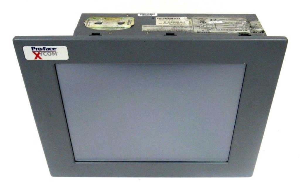
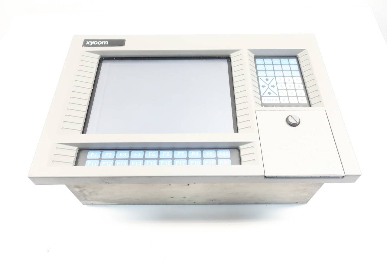
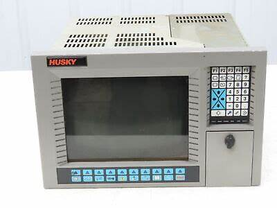
XYCOM 1546 PROFACE Industrial Computer
Product Overview
XYCOM 1546 PROFACE Industrial Computer with RS View 32 Batch Q302 is a high-performance computer device designed specifically for harsh industrial environments. It combines powerful computing power, rich interface configuration, and excellent stability, aiming to meet the needs of various complex industrial application scenarios such as industrial automation, process control, data acquisition and monitoring. This computer has a compact design, making it easy to install and deploy in environments with limited space such as factory workshops and control cabinets. At the same time, its sturdy and durable casing can effectively resist the effects of harsh factors such as vibration, impact, dust, and moisture, ensuring long-term reliable operation in various industrial sites.
Specification parameters
Processor: Supports Intel ® socket 478 Celeron ® M or Pentium ® M option, up to 2.0GHz, 400MHz or 533MHz front-end bus (depending on processor type), can efficiently handle various complex industrial control algorithms and data computation tasks.
Memory: Equipped with two 240 pin DDR2 DIMM slots, supporting multiple capacity options of 256MB, 512MB, 1GB, and 2GB. The system DRAM can reach 4M and can be expanded up to 32M, ensuring smooth program operation and efficient performance even during multitasking.
Storage: Provides CompactFlash ™ Option, supports up to 4GB, can be used to store important industrial data, program files, and system configuration information.
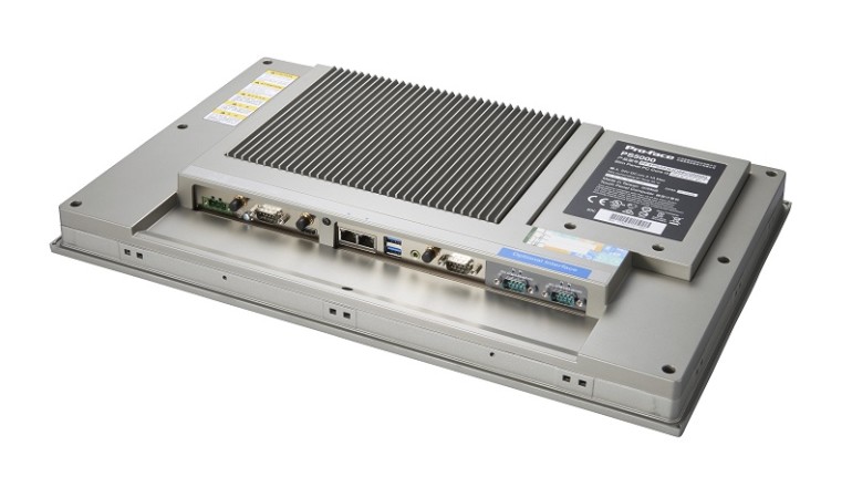
Interface: It has four serial COM ports, with three external ports configured as RS-232 and one configurable as RS-232, RS-422, or RS-485, making it convenient for serial communication with various industrial equipment; Simultaneously equipped with other common interfaces such as Ethernet interface, USB interface, etc., to meet the connection requirements of different devices.
Display: AGP video controller with 4M system memory, capable of providing clear and stable image display effects, meeting the display needs of industrial monitoring screens.
Power supply: The input voltage range is 100-240VAC, frequency is 50-60Hz, current is 1A, suitable for power supply environments in different regions, and has good power supply stability and anti-interference ability.
Environmental parameters: The maximum ambient temperature can reach 50 ° C, temperature code T6, in compliance with Class I, Division 2, Groups A, B, C, and D standards, and can operate stably in harsh environments such as high temperatures and potentially explosive gases.
Excessive Heat
The units withstand temperatures from 0º to 50ºC, and are fan-cooled.
To keep the temperature in range, the cooling air at the base of the system must not exceed 50°C.
Allocate proper spacing between internal components installed in the enclosure.
Electrical Noise
Electrical noise is seldom responsible for damaging components, unless extremely high energy or high voltage levels are present.
However, noise can cause temporary malfunctions, which can result in hazardous machine operation in certain applications.
Noise may be present only at certain times, may appear at widespread intervals, or in some cases may exist continuously.
Noise commonly enters through input, output, and power supply lines and may also be coupled through the capacitance between these lines and noise signal
carrier lines.
This usually results from the presence of high voltage or long, close spaced conductors.
When control lines are closely spaced with lines carrying large currents, the coupling of magnetic fields can also occur.
Use shielded cables to help minimize noise.
Potential noise generators include switching components, relays, solenoids, motors, and motor starters.
Refer to the relevant Federal, State/Provincial, and local electric codes, which provide data such as the size and types of conductors, color codes and connections necessary for safe grounding of electrical components.
It is recommended that the high voltage and low voltage cabling be separated and dressed apart. In particular,the AC cables and switch wiring should not be in the same conduit with all communication cables.
Line Voltage Variation
The unit’s power supply is built to operate with an input voltage range of 100 240VAC, while still allowing the system to function within its operating margin.
As long as the incoming voltage is adequate, the power supply provides all the logic voltages necessary to support the processor, memory, and I/O.
In cases in which the installation is subject to unusual AC line variations, use a constant voltage transformer to prevent the system from shutting down too often.
However, a first step toward the solution of the line variations is to correct any possible feed problem in the distribution system. If this correction does not solve
the problem, use a constant voltage transformer.
The constant voltage transformer stabilizes the input voltage to the 1546 and 1547 units by compensating for voltage changes at the primary in order to maintain a steady voltage at the secondary.
When using a constant voltage transformer, check that the power rating is sufficient to supply the unit.
AC Power Cable
A power cable must be created to supply power to the unit.
The following materials are needed:
A three-position power connector (supplied)
A braid/foil shielded power cable, terminated at power source end, with three 18 (1.0 mm), 16 (1.3 mm), or 14 (1.6 mm) AWG solid or stranded copper
wires, rated 80ºC or better
Perform the following steps to construct and attach the cable:
Cut wire cable to the desired length.
Strip 0.25-inch (6 mm) of insulation from the end of the conductor wire. No bare wire should be exposed when the cable is connected to the workstation.
Tin the wire ends with solder if using stranded wire.
This will keep the wire from fraying.
Insert the three wire ends of the power cable into the hole of the connector plug.
Bend the Protective Earth ground (PE) wire, the neutral (N) wire, and the line(L) wire around the corresponding screw. Be sure that no bare wires are exposed.
Tighten the three screws above the wires to hold them firmly in place..
Use the screw provided to secure and strain-relief the power cable inside the connector.
Plug the power cable into the power supply located on the side of the unit.
Install the plug retainer bracket over the plug (mandatory for hazardous location installations).
Once the power cable and other optional interface cables are installed, installation is complete.
DRAM and Additional DRAM Dual Inline Memory Modules DIMMs)
You can order the 1546/1547 system CPU factory-configured for many configurations of DRAM.
The system has two 240-pin DDR2 DIMMs that support 512, 1GB and 2GB options.
The maximum amount supported is 2GB.
You can reconfigure the DDR2 capacity by changing the DDR2 DIMMs on your board.
PC/AT® and PCI Boards
Check the memory and I/O configuration of the board you want to install so that it does not conflict with the CPU and I/O memory maps in your AIM4
documentation.
Remove the lid.
Remove the ORB screw from the desired slot.
Slide the PC/AT expansion board into the corresponding rail.
Push the board into the backplane connectors.
Secure the board by installing the screw through the hole in the board’s metal
ORB and into the top of the track.
Replace the lid.
Hazardous Locations Installation
Xycom Automation designed the 1546 and 1547 Node Box Industrial PCs to meet the requirements of Class I, Division 2 Hazardous Locations applications. Division 2 locations are those locations that are normally non-hazardous, but could become hazardous due to accidents that may expose the area to flammable vapors, gases or combustible dusts.
These systems have been designed as non-incendiary devices.
They are not intrinsically safe and should never be operated within a Division 1 (normally hazardous) location when installed as described here.
Nor should any peripheral interface device attached to these systems be located within Division 1 locations unless approved and/or certified diode barriers are placed in series with each individual signal and DC power line.
Any such installations are beyond the bounds of Xycom design intent.
Xycom Automation accepts no responsibility for installations of this equipment or any devices attached to this equipment in Division 1 locations.