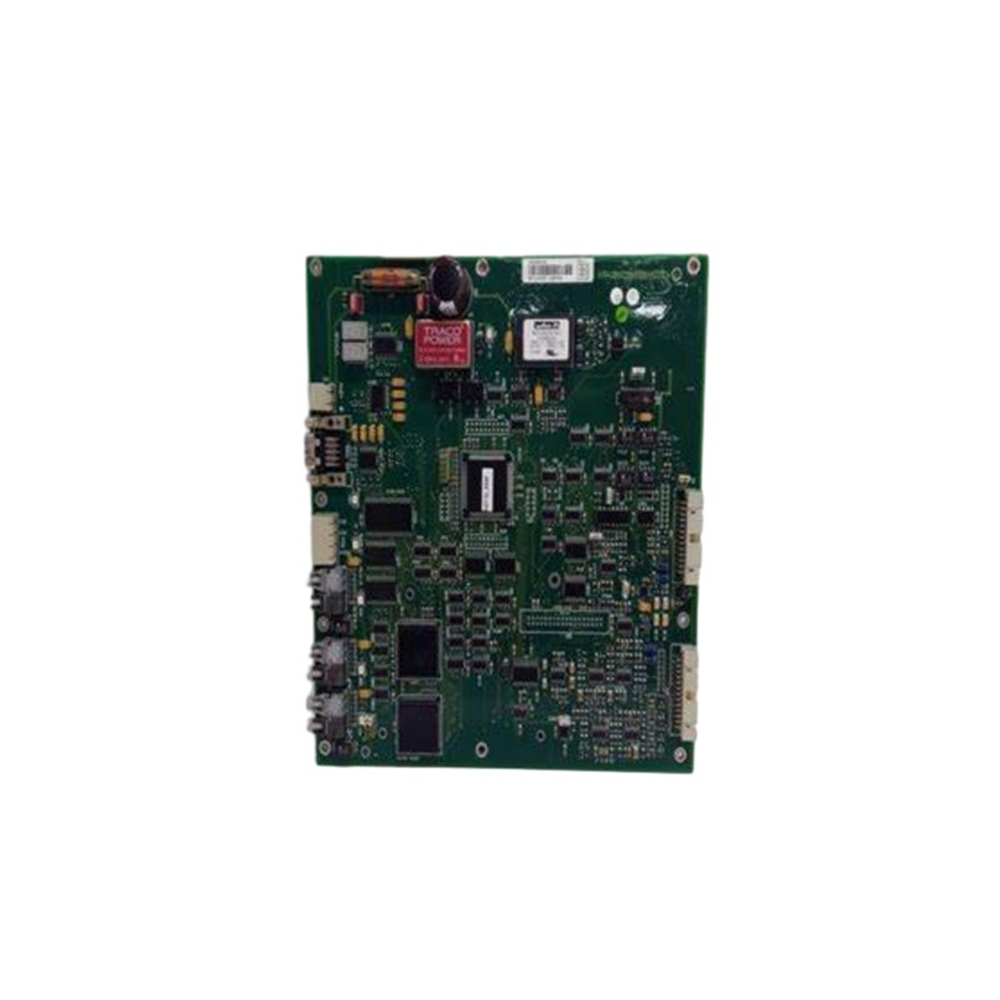
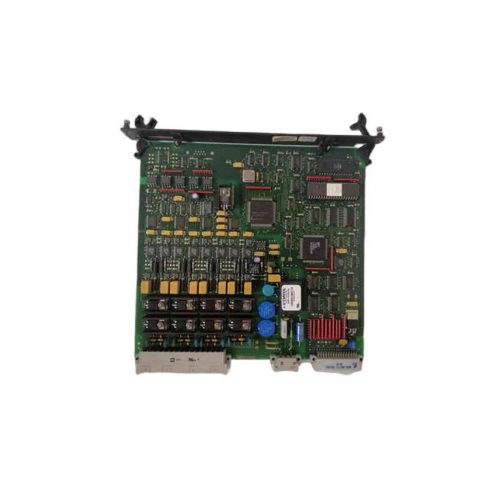
ABB 3ASC25H203-12 DAPC 100-12; Control board
ABB 3ASC25H203-12 DAPC 100-12; Control board, with CMT memory stick
Additional Information
ABB Type Designation: DAPC 100-57
Country of Origin: Sweden (SE)
Customs Tariff Number: 85371098
Gross Weight: 0.37 kg
Invoice Description: Control board, with CMT memory stick
Made To Order: No
Minimum Order Quantity: 1 piece
Order Multiple: 1 piece
Package Level 1 Units: 0 carton
Part Type: New
Product Name: Control board, with CMT memory stic
Product Net Weight: 0.37 kg
Quote Only: No
Selling Unit of Measure: piece
ABB 3ASC25H203-12 DAPC 100-12; Control board, with CMT memory stic
Product Definition and Positioning
Model name: ABB 3ASC25H203-12 DAPC 100-12 Control Board (including CMT Memory Stick) Product positioning: Industrial automation core control unit, integrated CMT (Compact Memory Technology) memory stick, designed specifically for mid to high end industrial control systems, supporting complex logic control, real-time data processing, and convenient program management, suitable for industrial scenarios that require high reliability and flexible configuration.
CMT Memory Stick Core Features
1. Hardware level data carrier
Storage capacity: comes standard with 8GB industrial grade flash memory and supports up to 32GB expansion
Interface type: Dedicated high-speed interface, data read/write speed up to 15MB/s (read)/8MB/s (write)
Security features:
Hardware Encryption: AES-128 Data Encryption Protection
Anti misoperation: plug-in interface with mechanical locking device
Seismic design: comply with IEC 60068-2-6 vibration standard
2. System level functional integration
Program loading: Supports offline configuration file import/export, complete system program migration within 5 minutes
Firmware upgrade: Control board firmware version iteration through memory stick, supporting breakpoint resume function
Data backup: Automatic periodic backup of key parameters (such as PID control parameters, equipment calibration values)
Core technical parameters
1. Hardware specifications of control board
Processor: Freescale PowerPC MPC5553, with a clock speed of 400MHz, supporting floating-point arithmetic units (FPUs)
Memory configuration: 256MB DDR3 cache+1GB NAND Flash (onboard)+CMT memory stick expansion storage
Communication interface: Ethernet: 2 × 10/100Mbps (supports Modbus TCP, EtherNet/IP)
Serial port: 3 × RS485/RS232 (supports Profibus DP) – Other: CAN 2.0B, USB 2.0 (only for CMT memory sticks)
I/O channel: Analog input: 8 × 16 bits (± 10V/4-20mA, supports cold end compensation)
Analog output: 4 × 16 bits (± 10V/4-20mA) – Digital input/output: 16 × 24V DC (optically isolated)
Working power supply: 24V DC (± 15%), power consumption ≤ 15W (including CMT memory stick)
Environmental adaptability: Temperature: -40 ℃~+70 ℃ (without cooling fan)
Humidity: 5%~95% (without condensation) – Protection level: IP20 (panel installation),
in compliance with IEC 61000-6-2 electromagnetic compatibility standard
2. Software functional parameters
Operating system: QNX Neutrino real-time operating system (RTOS), task scheduling accuracy ≤ 10 μ s
Programming support:
Compliant with IEC 61131-3 standards (LD/LAD, ST, FBD, SFC)
Support ABB Control Builder M engineering tool, compatible with third-party OPC UA servers
Data processing: Supports real-time data acquisition through 100+channels, with a minimum control cycle of 500 μ s
Core Control Function Architecture
CMT Memory Stick Workflow
Program deployment: Download the compiled control program to CMT memory stick through Control Builder M
System startup: After the control board is powered on, it automatically reads the configuration files (. cfg) and program files (. app) from the memory stick
Data exchange: Real time data during operation is synchronized to the memory stick according to the set cycle (1s~10min)
Fault recovery: When a system abnormality is detected, the latest valid backup data in the memory stick is automatically called up
Typical application scheme
Coordinated Control of Thermal Power Turbine
Configuration: Redundant deployment of 3 control boards, CMT memory sticks storing turbine start stop curves and load distribution strategies
Function:
Real time adjustment of valve opening (control accuracy ± 0.5%)
Memory stick automatic backup of PID parameters under variable load conditions
Support online modification of control strategies (through memory stick hot update program)
Intelligent warehousing and logistics system
Configuration: Single control board with dual CMT memory sticks (primary and backup redundancy)
Function:
Multi axis motion control (supporting 32 axis synchronization)
Memory stick stores coordinate data of each storage location and equipment calibration parameters
Quickly restore sorting system configuration through memory stick in case of malfunction
Installation and Maintenance Guide
1. CMT Memory Stick Operation Specification
Insertion/extraction: Be sure to operate in the power-off state, and hearing a “click” sound when inserting indicates that it is in place
Data backup: It is recommended to perform full backup through ABB Memory Tool software every week
Compatibility: Only supports ABB original CMT memory stick (part number: 3ASC25H205-01), third-party storage devices may cause system failure
2. Typical fault codes
E0101: CMT memory stick not recognized, check if the memory stick is securely inserted, restart the control board
E0203: Program checksum error, re download program to memory stick and restart system
E0315: Insufficient memory stick storage space, deleting outdated log files or replacing with a larger capacity memory stick
Industry standards and certifications
Electrical safety: compliant with IEC 61010-1 (pollution level 3)
Electromagnetic compatibility: EN 61326-1 (Class A for industrial environments)
Functional safety: Supports SIL 2 safety control (requires safety software package)