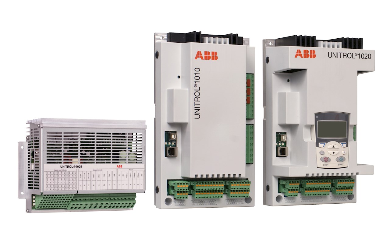
ABB ARC093AV1 Industrial Control High Frequency Module
Product Overview
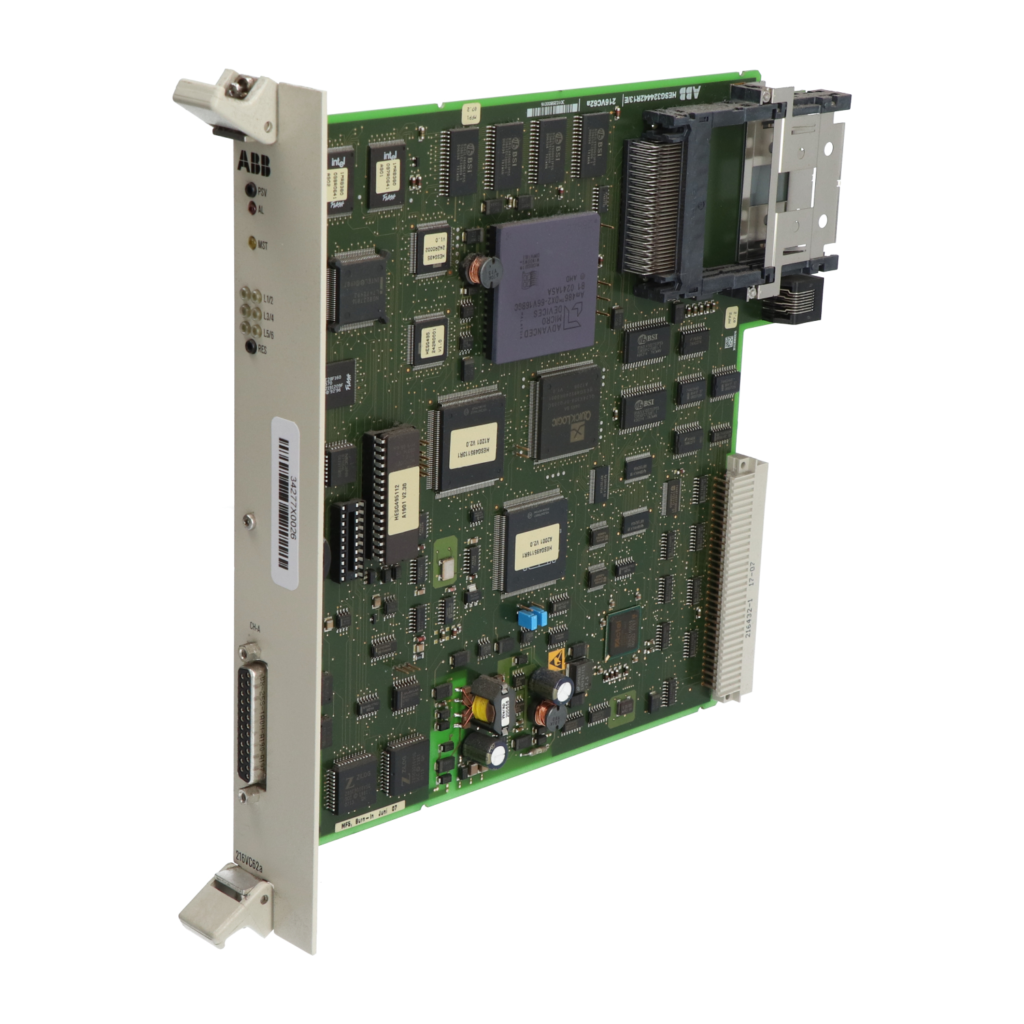
ABB ARC093AV1 Industrial Control High Frequency Module is a high-performance module developed specifically for the field of industrial automation control. In industrial automation systems, stable processing and precise control of high-frequency signals are crucial for efficient equipment operation and improved production quality. This module, with advanced technology and excellent performance, can achieve fast processing, transmission, and control of high-frequency signals, providing reliable support for various high-frequency application scenarios in industrial production. Its core function is to perform high-frequency modulation, amplification, and other processing on input electrical signals, and output high-frequency signals that meet industrial control requirements, thereby achieving precise control of equipment such as motor drives, high-frequency heating, and wireless communication. It is an essential key component in industrial automation control systems.
Specification parameters
working voltage
Input voltage range: AC 220V ± 10%, 50/60Hz; supports wide voltage input design to ensure stable operation in voltage fluctuation environments
-20 ℃ -+70 ℃, suitable for various harsh industrial environments such as high and low temperatures
Storage Temperature Range
-40 ℃ -+85 ℃, ensuring that the performance of the module is not affected in non working state
relative humidity
5% -95% (non condensing), with good moisture resistance
protection grade
IP20, Can prevent dust and solid foreign objects with a diameter greater than 12.5mm from entering, suitable for general industrial sites
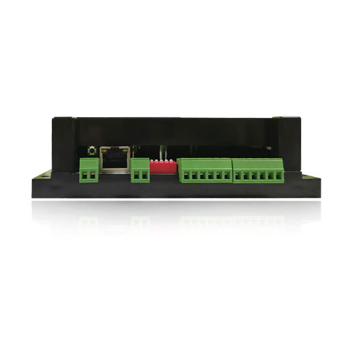
communication interface
Equipped with RS-485 and Ethernet interfaces, supporting communication protocols such as Modbus RTU and Profinet, facilitating data exchange and remote control with control systems such as PLC and DCS
Installation method
Support rail installation and panel installation, screw terminal block design for quick wiring, easy installation, saving debugging time
Core functions
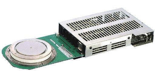
(1) High frequency signal processing and output
The ARC093AV1 module is capable of high-frequency modulation, amplification, filtering, and other processing of input electrical signals, converting them into high-frequency signal outputs that meet industrial control requirements. Through advanced internal signal processing circuits and algorithms, precise control of output signal parameters such as frequency, amplitude, and phase can be achieved, providing stable and accurate high-frequency driving signals for industrial equipment, ensuring the efficiency and stability of equipment operation. For example, in a high-frequency motor drive system, this module can output high-frequency signals of specific frequencies to control the motor to achieve high-speed and precise operation.
(2) Flexible parameter configuration and adjustment
Support flexible configuration and adjustment of output frequency, power, phase and other parameters through software or hardware. Users can quickly adjust module parameters and achieve personalized control solutions based on different industrial application scenarios and equipment requirements. Through the accompanying control software, the real-time monitoring of the operating status and parameters of the module is also possible, facilitating remote debugging and optimization, and improving the flexibility and adaptability of industrial production.
(3) Electrical isolation and protection
Adopting electrical isolation technology to achieve electrical isolation between input and output, effectively isolating the impact of external electromagnetic interference, voltage fluctuations, and other factors on modules and control systems. At the same time, the module has multiple protection functions such as overvoltage, overcurrent, and overheating. When abnormal situations occur, it can quickly cut off the output and issue alarm signals to protect the safety of the module itself and connected devices, reduce the risk of equipment damage, and improve the reliability and stability of the system.
(4) Communication and integration functions
The rich communication interfaces and support for multiple industrial communication protocols enable the ARC093AV1 module to easily integrate with industrial control systems such as PLC and DCS. Through the communication interface, the module can receive control instructions from the control system, enabling remote control and parameter setting; At the same time, real-time uploading of its own operating status, fault information, and other data to the control system facilitates centralized monitoring and management by operators, achieving intelligent and automated industrial production.
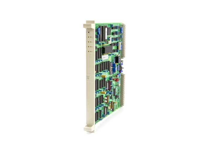
Working principle
The working principle of ARC093AV1 industrial control high-frequency module is based on high-frequency signal processing technology. After the input electrical signal enters the module, it first goes through a filtering circuit to remove clutter and interference from the signal, ensuring the purity of the input signal. Then, the signal enters the high-frequency modulation circuit and undergoes frequency, phase, and other modulation processing according to the set parameters, converting it into a high-frequency signal. The modulated high-frequency signal enters the power amplification circuit and is amplified by the power amplifier to meet the power requirements of industrial equipment.
The amplified high-frequency signal is further optimized through an output filtering circuit to remove harmonic and other interference components, ensuring the quality of the output signal. During the entire signal processing process, the control circuit inside the module monitors various parameters of the signal in real time and adjusts them according to the set values and feedback signals to ensure the stability and accuracy of the output signal. At the same time, the electrical isolation circuit isolates the input and output to prevent external interference from affecting the module and control system. The communication interface circuit is responsible for data exchange with external control systems, achieving remote control and status monitoring of modules.
Key advantages
(1) High performance and high precision
Having excellent high-frequency signal processing capabilities, it can achieve fast and accurate output of high-frequency signals, with high frequency accuracy and phase accuracy, meeting the strict requirements of industrial automation for high-precision control. In fields such as semiconductor manufacturing and precision machining that require extremely high precision, the accuracy and stability of equipment operation can be ensured, improving product quality and production efficiency.
(2) High reliability and stability
By using high-quality electronic components and advanced manufacturing processes, and undergoing rigorous quality testing and reliability testing, it can operate stably in harsh industrial environments. The electrical isolation and multiple protection functions effectively enhance the anti-interference ability and safety of the module, reduce the probability of equipment failure, lower maintenance costs, and ensure the continuity of industrial production.
(3) Flexible adaptability
Supports multiple installation methods and flexible parameter configuration, and can be customized according to different industrial application scenarios and equipment requirements. Rich communication interfaces and support for multiple communication protocols enable it to easily integrate into different industrial automation control systems, achieve collaborative work with other devices, and provide users with flexible solutions.
(4) Convenient maintenance and management
Remote monitoring and parameter setting can be achieved through communication interfaces, making it convenient for operators to manage and maintain modules. The module has a comprehensive fault diagnosis function, which can quickly locate the fault point and issue alarm signals, shorten the time for fault investigation and repair, and improve the availability and operation efficiency of the equipment.
Precautions
(1) Installation precautions
Before installation, ensure that the system is powered off to prevent electric shock accidents and module damage.
Choose a location with good ventilation, dryness, no severe vibration, and far from strong electromagnetic interference sources to install the module, avoiding adverse environments such as high temperature, humidity, and dust that can affect the module’s performance and service life.
Strictly follow the installation instructions for wiring, ensure that the input and output cables are firmly connected, distinguish the positive and negative poles of the signal, and avoid reverse connection. Use cables of appropriate specifications and take measures to secure and protect them to prevent abnormal signal transmission caused by cable pulling or wear.
When using guide rail installation, ensure that the guide rail is firmly installed, correctly clip the module into the guide rail and lock it; When using panel installation, use appropriate screws to secure the module to ensure smooth installation and avoid problems such as module looseness and poor contact caused by unstable installation.
(2) Precautions for use
Ensure that the input voltage is within the rated operating voltage range of the module, and it is strictly prohibited to connect voltages exceeding the rated value to prevent damage to the module. If the voltage is unstable, a suitable voltage regulator should be installed in the input circuit.
Avoid frequent adjustment of module parameters to prevent abnormal module operation caused by improper parameter settings. If parameters need to be adjusted, they should be done while the equipment is in a shutdown state and strictly follow the operation manual.
Regularly check the working status of the module and observe the display of the indicator lights. If the indicator light is abnormal (such as flashing, constantly on, or off), or if the module has abnormal signal output or unstable equipment operation, the machine should be stopped immediately for inspection. Refer to the module fault diagnosis guide, gradually investigate the cause of the fault, and contact professional technicians for repair if necessary.
During the operation of the module, it is forbidden to subject it to severe vibrations, collisions, or external forces to prevent internal components from loosening or being damaged, which may affect the normal operation of the module.
(3) Maintenance precautions
Regularly clean the surface dust and dirt of the module, keep it clean, and prevent dust accumulation from affecting heat dissipation and electrical performance. When cleaning, use a dry, soft brush or compressed air, avoid using damp cloths or corrosive cleaning agents to prevent damage to the module housing and internal circuits.
Regularly check the wiring terminals to ensure that the wiring is secure, free from looseness or oxidation. If loose terminals are found, use appropriate tools to tighten them; If the terminal oxidizes, use sandpaper or specialized cleaning agents for cleaning treatment to ensure good electrical connection performance of the wiring.
Regularly perform performance testing and calibration on modules based on their usage frequency and working environment to ensure that all parameters and indicators meet the requirements. According to the module service life and enterprise equipment update plan, timely module replacement and upgrading are carried out to ensure the performance and reliability of industrial automation systems.
Application scenarios
(1) High frequency motor drive
The application of high-frequency motors is becoming increasingly widespread in equipment such as CNC machine tools, textile machinery, and printing machinery. The ARC093AV1 industrial control high-frequency module can serve as the driving core for high-frequency motors. By outputting precise high-frequency signals, it controls the motor to achieve high-speed and precise operation, improving the machining accuracy and production efficiency of the equipment. For example, in CNC machine tools, high-frequency motor drive can achieve high-speed rotation and precise feed of cutting tools, improving the machining quality and surface smoothness of parts.
(2) High frequency heating
High frequency heating technology has been widely used in industries such as metal heat treatment, plastic welding, and food processing. The ARC093AV1 module is capable of outputting high-frequency signals of specific frequencies and powers, driving the induction coil to generate a high-frequency magnetic field, which generates eddy currents inside the heated object and generates heat, achieving fast and efficient heating. In metal heat treatment, local heating, quenching, annealing and other treatments can be carried out on metal parts to improve the performance of metal materials; In plastic welding, it is possible to achieve fast and secure welding of plastic components.
(3) Wireless communication
In the field of industrial wireless communication, such as wireless sensor networks, industrial Internet of Things, etc., ARC093AV1 module can be used for the transmission and reception of high-frequency signals. By modulating and amplifying high-frequency signals, long-distance and high-speed data transmission is achieved, providing reliable support for wireless communication between industrial equipment. For example, in industrial production sites, wireless sensors transmit the collected data in the form of high-frequency signals to the monitoring center through the ARC093AV1 module, achieving real-time monitoring and remote control of the production process.
(4) In the field of new energy
ARC093AV1 module also plays an important role in fields such as new energy generation and electric vehicle charging. In the process of energy conversion and grid connection in new energy generation, such as wind power and solar power, high-frequency signals need to be processed and controlled to achieve efficient conversion and stable output of electrical energy. In the field of electric vehicle charging, this module can be used for controlling high-frequency charging stations, achieving fast and safe charging, improving charging efficiency and equipment compatibility.