Call us 24/7uaedcs@163.com
Welcome to the official website of CNIACS Automation Technology Co., Ltd!
Call us 24/7uaedcs@163.com

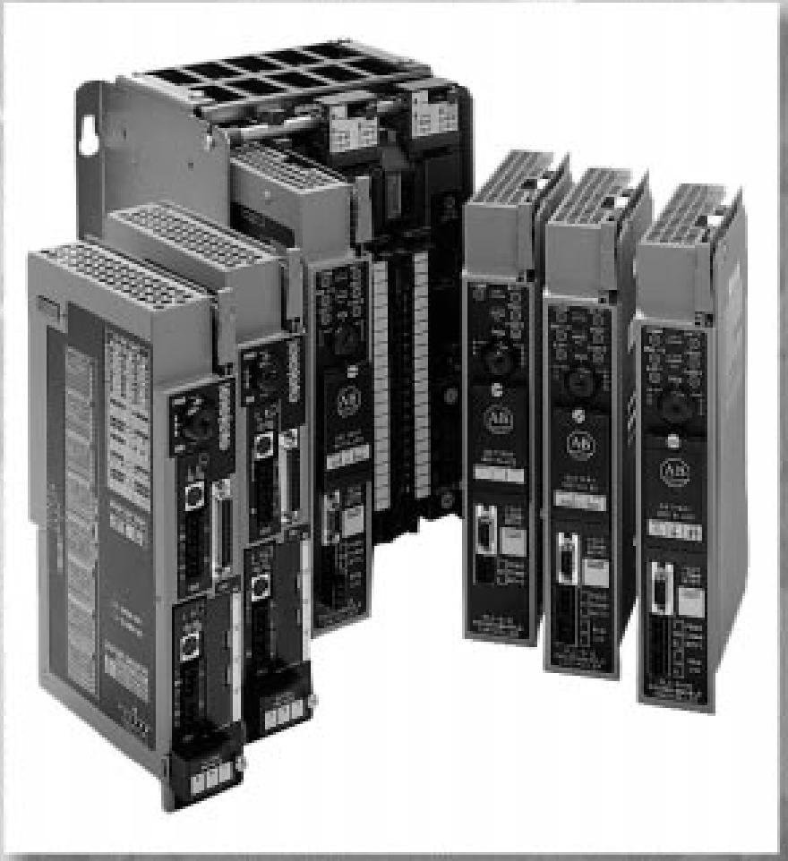
AB 1785 PLC-5 Programmable Controller System

System Overview: PLC-5 programmable controller system can be connected to a variety of devices, support EtherNet/IP, ControlNet, DeviceNet and other networks, with a variety of programming languages and software tools to meet different user needs. Users need to draw the system block diagram according to the actual situation, determine the number of controllers and communication methods, and also can choose the hot standby programme to enhance system reliability.
Selection Steps

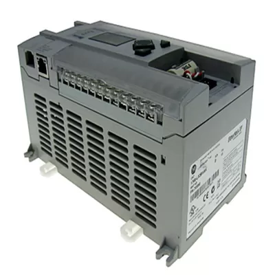
I/O Module Selection: Covering 1771, 1746, 1794 and other series, each series has different characteristics and application scenarios. 1771 series has a wide range of types, with input and output modules of different voltage levels and number of channels; 1746 series is SLC 500 I/O, which can be connected to ControlNet through specific adapters; 1794 FLEX I/O is cost-effective and supports various networks. The 1794 FLEX I/O is cost-effective and supports a wide range of networks.

Communication network options: Includes NetLinx networks (e.g., EtherNet/IP, ControlNet, DeviceNet) and serial networks (e.g., RS-232, DH+) EtherNet/IP is Ethernet-based and Web-enabled; ControlNet provides high-speed deterministic communication; DeviceNet reduces wiring; serial networks are used for device-specific connections. DeviceNet reduces wiring; serial networks are used for device-specific connections.

Controller Selection: It is divided into ordinary PLC-5, EtherNet PLC-5, ControlNet PLC-5, etc. Different types have differences in memory, I/O capability, network interface, etc. Users need to select according to system requirements. Users need to choose according to the system requirements, and can also be equipped with EEPROM and battery, and at the same time to consider the frame selection, installation size and power supply selection.

Software selection: Programming software such as RSLogix 5 for application programming; communication software RSLinx for device communication; network configuration software RSNetWorx for configuration of network parameters; and software such as RSLogix Emulate 5, as well as relevant training courses and work instruction materials.

Special features
Powerful connectivity: It can connect to devices within the range of EtherNet/IP, ControlNet, DeviceNet, SLC 500, ControlLogix, MicroLogix, etc., and also communicate with computers, servers, etc., which realises a wide range of device interconnections and meets the needs of device connectivity in different industrial scenarios. Supporting a variety of network interfaces, users can choose the best network configuration according to the actual needs, to achieve control and information data routing between different networks, to ensure the efficient operation of the system.

Flexible network communication: The NetLinx network architecture (EtherNet/IP, ControlNet, DeviceNet) enables seamless integration of all components in the system, reducing installation costs and improving efficiency. etherNet/IP is Ethernet-based and web-enabled, making it easy to create customised web pages to provide process information; ControlNet provides high-speed, deterministic I/O transfer for control scenarios requiring high real-time performance; DeviceNet reduces wiring and system complexity. It supports serial network connection, such as RS-232, RS-423, RS422A, and can communicate with specific devices through DF1 and ASCII protocols, which is suitable for devices that do not require high communication speed but need simple connection.

Rich programming and software support: support for a variety of programming languages, such as Structured Text (ST), Function Block (FB), Sequential Function Flowchart (SFC) and Ladder Diagram, to meet the programming habits of different users and application requirements, convenient for users to carry out program development, maintenance and troubleshooting. A variety of software tools are provided, RSLogix 5 for application programming, RSLinx for inter-device communication, RSNetWorx for network parameter configuration, RSLogix Emulate 5 for simulation debugging, and ViewAnyWare to meet the needs of monitoring and operation at different levels.

Variety of controllers: According to different application scenarios and needs, we provide various types of controllers, such as common PLC-5, EtherNet PLC-5, ControlNet PLC-5, etc.. Different types of controllers differ in memory size, number of I/O points, network interface, backplane current load, etc., so users can choose flexibly according to actual needs. Some of the controllers have special functions, such as ControlNet PLC-5 controller supports hot standby programme, in which the second controller can take over the control outputs quickly when the main controller is down to ensure the stability and reliability of the system.

Abundant I/O Module Types: There are many types of I/O modules, including 1771, 1746, 1794, 1797, 1791D, etc., each with different voltage levels, channel numbers and functional features, which can meet the input/output requirements of various industrial sites. 1771 series I/O modules are abundant in types, which cover a wide range of input/output modules in terms of voltage levels and signal types; The 1794 FLEX I/O is cost-effective and highly scalable, and the 1791D CompactBlock I/O is designed for small form factor applications with integrated DeviceLogix functionality.

AB 1785-PFB PLC-5 PROFIBUS Local Station Manager

Technical specifications
Communication interface specifications: Connected via RS-232 cable, one end of the cable is connected to the computer, the other end is connected to the 9-pin female connector, the specific pin definition is clear, Pin 4 is used for the module to transmit data to the computer (TX), Pin 3 is used for the computer to receive data to the module (RX), Pin 1 as the data ground (GND). This shows that the device uses the RS-232 standard interface for data transmission, this interface is widely used in the field of industrial control, has a certain degree of versatility and stability, to meet the basic data communication needs between the device and the computer.

Software environment requirements: need to run on Microsoft Windows 3.1 or higher version of the operating system. This requirement restricts the scope of the software environment used, ensures compatibility with specific operating systems, and also implies that the software architecture and functional design of the Local Station Manager are developed based on the characteristics and standards of these operating systems, and users need to ensure that the computer meets the conditions of this software environment when using it.

Bus Parameters: Bus parameters can be set, including local address, baud rate, maximum address and message timeout. Baud rate is commonly set to 500Kbaud, 187.5Kbaud and so on. These parameters can be set for the user according to different industrial field environment and equipment requirements for flexible configuration provides the possibility of different baud rate settings will affect the speed and stability of data transmission, the user can choose the optimal configuration according to the actual situation.

Module Status Indication: The module status is displayed through a special window, which contains various statuses, such as ‘Operational’ indicates that the module has been configured for communication; ‘No Communication’ indicates that the module is busy, No Communication’ indicates that the module is busy, an error has occurred, or the RS-232 cable is not connected. These status indicators provide users with intuitive information about the module’s operation, which helps to find and solve problems in time, and to judge whether the module’s working status is normal or not, so as to take corresponding measures.

Prerequisites for Use and Connection and Installation: To use the Local Station Manager, you need to master the operation of Microsoft Windows 3.1 or later, and connect the computer and the PROFIBUS coprocessor with the RS-232 cable, and connect them according to the specific pins. Afterwards, insert the floppy diskette of the Local Station Manager into the drive of the computer and install it by entering the installation commands via the ‘Execute’ option in the ‘File’ menu. The installer will copy the files to the default directory and you can choose whether or not to modify the SYSTEM.INI file. file.

Basic operation guide
Open and Language Selection: After starting Windows, double click the AB_PROFIBUS icon to open the Local Station Manager, and then double click the Local Station Manager icon or press the Enter key to select the language from English, German and French to enter the main interface.
Use of help tools: Click the ‘?’ icon to get context help, press F1 key or select ‘Index’ in ‘Help’ menu to view the help index, you can continue to browse or exit the help tool by menu operation.
Communication Port Selection: Click the ‘Settings’ icon or select ‘COM Port’ from the ‘Settings’ menu to select the communication port of the computer to which the RS-232 cable is connected. Three windows will be displayed, including ‘Module Status’, in which ‘Module Status’ window will display different status of the module.

Function operation details
Check battery level and switch: Click ‘MOD INFO’ icon or select ‘Module Info’ from ‘Info’ menu to check the battery level and switch setting according to the module status. If the module status is ‘no communication’, you need to check the connection and port settings.
Setting and verifying bus parameters: Click ‘Bus’ icon or select ‘Bus Parameters’ from ‘Configuration’ menu, you can choose default parameters or manually input new parameters, click ‘OK’ before you need to check the connection and port settings. You can select the default parameters or manually enter new parameters, set switch 2 to ‘Off’ before clicking ‘OK’ to verify the new parameters.
Monitor system events: Click ‘EVT’ icon or select ‘Module Events’ from ‘Monitor’ menu, you can view the time, source and explanation of module events. By comparing the time, you can determine the interval of the event, and according to the source and explanation, you can analyse the cause of the event.

Other operations
Reset operation: Click ‘RES MOD’ icon or select ‘Module Reset’ from ‘Monitor’ menu to reset the module, click ‘RES COM’ icon or select ‘Module Reset’ from ‘Monitor’ menu to reset the module. Communication can be reset by clicking ‘COM’ icon or selecting ‘Communication Reset’ from ‘Monitor’ menu. The reset operation needs to confirm the prompt message and the LED of the module will change accordingly during the reset process.
Address translation: By clicking on the ‘MB HEX’ icon or selecting ‘Address Translator’ from the ‘Utilities’ menu, you can translate between PLC-5 data form addresses (symbolic) and PROFIBUS physical addresses (32-bit). PROFIBUS physical address (32 bit hexadecimal).

AB 1785-L40E Ethernet PLC-5 Programmable Controllers

Technical Specifications
Environmental Specifications
Temperature Range: Operating temperature range of 0 to 60°C (32 to 140°F) in accordance with IEC 60068 – 2 – 1 (Test Ad, Operating Cold), IEC 60068 – 2 – 2 (Test Bd, Operating Dry Heat), and IEC 60068 – 2 – 14 (Test Nb, Operating Thermal Shock). (Test Nb, Operating Thermal Shock), a temperature range that meets the requirements for stable operation in most common industrial environments. The non-operating temperature range is – 40 to 85°C (- 40 to 185°F) according to IEC 60068 – 2 – 1 (Test Ab, Un-packaged Nonoperating Cold), IEC 60068 – 2 – 2 (Test Bc, Un-packaged Nonoperating Dry Heat), and IEC 60068 – 2 – 14 (Test Nb, Operating Thermal Shock). and IEC 60068 – 2 – 14 (Test Na, Un-packaged Nonoperating Thermal Shock) to ensure the safety and stability of the equipment during storage and transport.
Humidity requirements: Relative humidity requirements of 5% to 95% (non-condensing), according to IEC 60068 – 2 – 30 (Test Db, Un – packaged Nonoperating Damp Heat) standard, this humidity range can effectively avoid the humidity problems caused by electrical shorts or corrosion of the components and other faults, to ensure the normal operation of the internal circuitry of the equipment.
Altitude and Pollution Level: Applicable to areas below 2000 metres above sea level, pollution level 2, can work normally in general industrial environments, where the equipment can withstand a certain degree of dust, moisture and other pollution, to maintain stable performance.
Electromagnetic compatibility: Group 1, Class A industrial equipment, in accordance with CISPR 11 standards. When used in other environments, additional measures may be required to ensure electromagnetic compatibility in order to avoid electromagnetic interference with the equipment or interference with other equipment.

Electrical performance specifications
Power Parameters: The maximum power consumption is 3.6A @5V dc, and the maximum power dissipation is 18.9W, which determines the power consumption of the device during operation. Users need to take these parameters into consideration when configuring the power supply system to ensure that the power supply can stably supply power to the device.
Insulation and Voltage Resistance: The basic insulation between the communication ports and the backplane is 50V and can withstand 500V rms for 60 seconds. This feature ensures the safety of the device in terms of electrical insulation, effectively preventing electrical faults and the risk of electric shock, ensuring the safety of operators and equipment.

Mechanical specifications
Vibration resistance: 2g @10 to 500 Hz under operating conditions in accordance with IEC 60068 – 2 – 6 (Test Fc, Operating). This allows the equipment to remain stable in vibration environments on industrial sites, such as those where large machinery and equipment are operated, and reduces the likelihood of loosening or damage to internal components due to vibration.
Shock resistance: 30g for operational shock and 50g for non-operational shock according to IEC 60068 – 2 – 27:1987 (Test Ea, Unpackaged shock). This means that when the device is subjected to a certain degree of shock, such as bumps during transport or accidental collisions, it has a certain degree of shock resistance, which effectively protects the internal precision components and maintains the normal function of the device.

Certifications and compliance specifications: UL, CSA, CE, C-Tick, etc. UL certification indicates that the equipment meets the safety standards of Underwriters Laboratories in the U.S.; CSA certification means that it complies with the relevant standards of the Canadian Standards Association; CE certification means that it meets the relevant directives in the European market; and C-Tick certification complies with Australia’s radiocommunication regulations. These certifications ensure the safe use of the product and market access in different regions.
BASIC INFORMATION AND SAFETY TIPS: This manual focuses on the Ethernet PLC-5 programmable controllers, models 1785-L20E, 1785-L40E, 1785-L80E (Series F), and is intended to guide the user through installation and troubleshooting. The manual emphasises the differences between solid-state and electromechanical equipment, reminds the user to ensure that the equipment is used appropriately, and states that Rockwell Automation is not responsible for consequential damages resulting from the use of the equipment. The manual also contains a number of safety tips for safe operation in hazardous environments, static electricity protection, and other areas.

Installation Procedure
Pre-installation Preparation: Before installation, you need to make good protection against static electricity, such as touching grounded objects, wearing a grounded wrist strap, avoiding touching circuit board connectors and components, etc., and storing the equipment in anti-static packaging.
Hardware installation: I/O chassis installation, configuration (set the backplane switch, power configuration jumper and keying tape), power supply installation, controller installation (set the DH + station address, serial port configuration, installation of batteries), the installation process should pay attention to the details of the various steps and the relevant warning information, such as connecting or disconnecting the battery may generate an electric arc, the need to be in the power failure or non-hazardous environment.
System Connection and Test: After completing the hardware installation, power on the system. At this point, the programming software may indicate a RAM error, which can be acted upon according to the key switch position. Connect the PC to the controller and refer to the relevant manual for details.

New Features
Network Configuration: The controller’s Channel 2 communication ports are equipped with RJ-45 connectors and support BOOTP, DHCP, or static IP address settings, auto-negotiation of speed, full/half-duplex port settings, and 10/100 Mbps speed selection.
Other functions: With mail client function, it can send mails through mail relay server; it supports HTTP Web Server and Simple Network Management Protocol (SNMP) function, which can be enabled or disabled in Channel 2 configuration, and the controller needs to be restarted to take effect after changing the relevant settings.
Troubleshooting: Diagnose the faults by observing the colour and status of the BATT, PROC, FORCE, COMM and other lights on the controller; red BATT light indicates low battery, which needs to be replaced in time; blinking red PROC light may indicate that there is an error in RSLogix 5 during download or operation, which can be dealt with by checking the fault bits in the status file. Faults on different communication channels (e.g., Remote I/O, DH+, Ethernet) can also be investigated and resolved based on the status of the corresponding indicator.

AB 1785-L20C15 ControlNet PLC-5 Programmable Controllers

Installation Process
Pre-preparation: Check the processor package and make sure the accessories are complete, including the processor, battery, and related documents. Prepare the tools and equipment needed for installation, such as I/O chassis, power supply, screwdriver, etc., and record the Ethernet hardware address.
Installation operation: Pay attention to the model and operation specification when installing the battery to prevent electrostatic discharge. Set the I/O chassis back panel switches, configuration plugs and keystrip to select the DH+ station address, serial interface, and ControlNet network address. When plugging the processor into the I/O chassis, be sure to operate it without power to avoid electrical arcing. When connecting remote I/O, DH+, and ControlNet networks, follow cable length and connection specifications and use appropriate terminating resistors.

System planning and use
ControlNet I/O Principle: The ControlNet system enables high-speed, repeatable, and deterministic I/O transfer, supporting the coexistence of control and message information on the same physical medium. Data transfers are scheduled and unscheduled, with scheduled data transfers being continuous and asynchronous for ladder logic program scans, and unscheduled data transfers being used in scenarios where determinism is not required.

Connections and Mapping: introduces the various connection types, such as exclusive owner, input-only, listen-only, and redundant owner connections, as well as the rules for combining them.I/O Mapping involves the creation and maintenance of I/O mapping tables, designating storage locations for the different types of I/O data transfers, as well as reserving space for non-ControlNet I/O.
Optimisation strategy: The use of the I/O image table can be optimised by reasonably arranging the position of the I/O modules, such as placing the less used module types on the left side, and placing the modules that do not need the space of the I/O image table on the right side. There are two methods of optimising complementary without slot and optimising complementary with slot, which are often used in combination in practical applications.

Software Configuration and Programming
Software tools: RSNetWorx for ControlNet software is used to define network parameters and monitor the status of I/O mapping entries; RSLogix 5 software is used to input user programme files, configure modules, etc.; RSLinx software provides the network interface and polls network devices.
Project Operation: When uploading and downloading software projects, ensure that the ControlNet configuration information in the RSLogix 5 project file and the RSNetWorx project file is consistent. Once downloaded, you can use the RSNetWorx software to perform verification activities such as verifying keeper signatures and scanner signatures.
Command usage: ControlNet supports various commands, such as the Message (MSG) command for sending message commands within the network, which can be used for multi-hop communication; the ControlNet I/O Transfer (CIO) command for non-discrete I/O data transfer; and the Immediate Data Input (IDI) and Immediate Data Output (IDO) commands, etc., which have their own scenarios and methods of usage. There are also Immediate Data Input (IDI) and Immediate Data Output (IDO) instructions.

Monitoring and Troubleshooting
Status monitoring: The general operation status of the processor can be understood through the various status indicators on the processor, such as BATT, PROC, FORCE, COMM, etc.; the ControlNet status indicator reflects the operation status of the ControlNet network; and the DH+/RIO status indicators are used to monitor the status of the data highway and the remote I/Os.
Troubleshooting: The common fault codes and their meanings are introduced, for example, 200 indicates that the ControlNet scheduling output data is lost and it is necessary to check whether there is any electrical noise in the network. Corrective action is provided for each fault code.
Technical Specifications and References

Processor specifications: covers the electrical, environmental, mechanical, and communication parameters of the processor, such as backplane current, operating temperature, network update time, etc. It also introduces the available ink cartridges, batteries, memory modules, and so on.
Status File and Instruction Set: The contents stored in each word of the processor status file are described in detail, including arithmetic flags, processor status and flags, and fault codes. The instruction set of ControlNet is introduced, including I/O transfer instructions, message instructions, immediate data I/O instructions, etc., as well as the execution time and memory requirements of the instructions.

Performance Advantages
Efficient and Reliable Communication Performance
High-speed deterministic transmission: ControlNet network is designed for high-speed, repeatable and deterministic I/O transmission, ensuring stable coexistence of control and message information on the same physical medium. In industrial production scenarios, for time-sensitive control commands and real-time data acquisition, it can ensure the timeliness and accuracy of data transmission and avoid production failures caused by delayed or unstable data transmission. In automotive production lines, a large amount of sensor data and equipment control commands are transmitted through the ControlNet network, and its deterministic transmission characteristics ensure the accurate operation of the production line.

Multiple communication methods: A variety of communication methods are supported, including Scheduled Data-Transfer Operations (continuous and asynchronous in ladder logic programme scanning) and Unscheduled Data-Transfer Operations (for scenarios with non-deterministic requirements). This flexible communication mechanism allows the controller to choose the most appropriate communication method for different application requirements, which not only meets the needs of real-time control, but also handles non-deterministic messaging such as programming devices and human-machine interface (HMI) devices, and improves the overall communication efficiency of the system.

Powerful data processing capabilities
Efficient data transfer mechanism: Both discrete I/O data transfer and non-discrete I/O data transfer can be performed in an efficient manner. Discrete I/O data transfers can be configured in the I/O map table for deterministic and repeatable operations; non-discrete I/O data transfers can be configured in the I/O map table or updated using the ControlNet I/O Transfer (CIO) instruction, and have the same priority as discrete I/O data transfers, which effectively improves the speed and efficiency of data processing. This effectively improves the speed and efficiency of data processing. The controller’s non-discrete I/O data transfer capability meets the high demand for real-time processing of large amounts of analogue data in chemical production processes.

Supports multi-processor control: multiple ControlNet PLC-5 processors can update the I/O adapters at the same time, and any processor can control the adapters on the network, send CIO commands, and carry out peer-to-peer communication, which realises distributed control and cooperative work of the system, enhances the overall data processing capability and control flexibility of the system, and is suitable for multi-node control of large-scale complex industrial systems. It is suitable for multi-node control of large and complex industrial systems.

Flexible Configuration
Flexible I/O mapping: I/O mapping is highly flexible, users can map I/O data into I/O image table or DIF/DOF file according to the actual demand, and the mapping position and size of input and output data can be adjusted according to the specific situation. This flexibility enables the controller to adapt to different I/O device layouts and data processing requirements, improving the adaptability and scalability of the system configuration. In industrial automation projects of different sizes, the I/O mapping can be flexibly adjusted according to the number and type of I/O devices to meet the specific needs of the project.
Optimized I/O Configuration: A variety of methods are provided to optimize I/O configuration, such as optimizing the use of I/O image table, which can make full use of I/O resources and reduce the waste of resources by adjusting the location of modules and choosing appropriate addressing modes. In practical applications, according to the I/O demand and resources of the system, you can choose to optimise the slotless complementary or optimise the slotted complementary method to improve the efficiency of I/O resources.

Easy Diagnosis and Maintenance
Comprehensive Fault Diagnosis: Equipped with a perfect fault diagnosis mechanism, it can quickly and accurately determine the system’s operation status and fault types through the various status indicators (such as BATT, PROC, FORCE, COMM, etc.) on the processor, as well as the ControlNet status indicator and the DH+/RIO status indicator. Combined with detailed fault codes (such as those stored in S:12 in the processor status file), it can provide in-depth understanding of the cause of the fault, and provide strong support for troubleshooting and repair. When a system failure occurs, technicians can quickly locate the point of failure and shorten troubleshooting time based on the indicator status and fault codes.

Convenient monitoring and maintenance: The configuration and status of the ControlNet network can be comprehensively monitored with software tools such as RSNetWorx for ControlNet, RSLogix5, and RSLinx, which can be used to define network parameters and monitor the status of I/O map entries; RSLogix5 can be used to monitor ControlNet diagnostic files and manage user programme files; RSLinx can be used to poll network devices and monitor station diagnostic information. The coordinated use of these software tools facilitates the daily maintenance and management of the system, and improves the reliability and stability of the system.

AB 1785-ENET PLC-5 Ethernet Interface Module

Basic information: This manual is intended for control engineers who are responsible for designing, installing, programming, or debugging the use of this module, and who have knowledge of PLC-5 programmable controller products and Ethernet-related topics such as TCP/IP protocols, Internet addressing, etc. The manual is intended to guide the user in the installation and configuration of this interface module to enable communication over Ethernet. The manual is intended to guide the user in the installation and configuration of the interface module for communication over Ethernet.

Installation Guide
Preparation: Prepare equipment and tools such as the PLC-5 Ethernet interface module, 58-pin connector plug, related manuals, record the Ethernet hardware address, and take precautions against static electricity.
Installation Procedure: Firstly, carefully align and insert the connector plug into the PLC-5 processor, then connect the interface module to the processor and tighten the screws, and finally install the combination module into the left slot of the 1771 I/O chassis, and make sure the power of the chassis is switched off during the whole installation.
Disassembly points: first cut off the power, lift the locking lever, and at the same time lift the ejector tab to remove the module, be careful to avoid damaging the components when separating the module from the processor.

Configuration
IP address assignment: Each Ethernet hardware address needs to be configured with a unique IP address, which can be entered manually in the programming software or dynamically assigned through the server using the BOOTP protocol.
Manual configuration: In the programming software, first disable BOOTP and then enter the Ethernet-specific information such as diagnostic file number, IP address, etc. in sequence.
BOOTP Configuration: There should be a BOOTP server in the network, edit the BOOTPTAB file, input the module’s hardware address, IP address and other information, save it, run the server and restart the chassis.

Communication Function
Status monitoring: Judge the operation status of the module by observing the LEDs, such as the STAT light is always on in green which indicates normal connection to the network, and blinking red which indicates a fault. You can also check the Ethernet status data with the help of diagnostic files to understand the communication situation.
Use of MSG command: This command is used to transfer data, and when using it, you need to set the control block and command parameters, such as command type, data address, number of elements to be transferred, etc., and it can be used to communicate with a variety of devices.
Communication with ControlLogix devices: With the ControlLogix 1756-ENET module, configure the MSG instruction and related parameters, such as setting the Link ID number, to communicate with other PLCs and SLC processors.

Specifications and Diagnostics
Module specifications: Covering electrical, environmental, mechanical and other parameters, such as backplane current of 2.2A, operating temperature of 0-60°C, support for 64 simultaneous connections, etc., with CSA, UL, CE and other approvals.
Performance Data: Provides PLC to PLC and workstation to PLC performance data under different operation and data volume, such as MSG per second, time per MSG, words per second, etc.
SNMP Management Information Base: The module supports SNMP, and the MIB II data set contains management information on system, interface, UDP, IP, ICMP, TCP, and so on.
Error Code: When the status LED blinks red, it indicates a fault, and the error code is displayed through a specific blinking sequence, according to which the type of fault can be judged, e.g. 01 means that the General 68000 test has failed.

Technical specification parameters
Electrical parameters: The backplane current is 2.2A, this parameter determines the amount of current obtained from the backplane when the module is working, a stable current supply is the basis for normal operation of the module. The heat dissipation is 37.54 BTU/hr, which reflects the rate of heat generated by the module in the working process. Reasonable heat dissipation design helps to maintain the stable working temperature of the module, avoiding performance degradation or failure due to overheating.
Environmental parameters: the working temperature range is 0 to 60°C (32 – 140°F), the storage temperature range is -40 to 85°C (-40 – 185°F), this wide range of temperature adaptability enables the module to be stored and used in different environmental conditions, whether in cold storage environment or hot industrial production site, can ensure a certain degree of adaptability. The relative humidity requirement of 5% to 95% (non-condensing) ensures that under different humidity environments, the module will not cause short-circuit and other problems due to water vapour condensation inside the module, which guarantees the electrical performance and stability of the module.

Mechanical parameters: In terms of impact, it can withstand 30 g peak acceleration with a duration of 11 ± 1 ms during operation, and 50 g peak acceleration with a duration of 11 ± 1 ms during non-operation. This makes the module resistant to mechanical shocks, such as bumps during transport of equipment and vibrations at industrial sites, and reduces the risk of damage to internal components caused by shocks. Vibration parameters are 2 g @ 10 to 500 Hz, 0.012 inches peak-to-peak displacement, indicating that the module in a certain frequency and displacement range of anti-vibration performance is good, can adapt to the common vibration in industrial environments, to ensure that the module in the vibration of the reliable operation of the environment.

Communication Parameters: Adopting Ethernet (TCP/IP protocol) for communication, network connection is achieved through the 15-pin AUI transceiver port, which ensures stable communication with other devices that support TCP/IP protocol. It supports 64 simultaneous connections, which means that the module is able to establish connections with multiple devices at the same time, meeting the needs of multi-device communication in complex industrial networks. At the same time, the availability of 512 unsolicited definitions (for the RSLinx and INTERCHANGE software packages) provides more flexibility and scalability for data interaction between the associated software and the module.

Other parameters: The module fits into the second left slot of the 1771-A1B, -A2B, -A3B, -A3B1, -A4B chassis and is connected to the processor. The clear mounting position specification helps users to accurately install the module in the system integration and ensures the structural integrity and stability of the system. The module’s keyless design simplifies installation by eliminating the need for complex keying operations. At 0.95 kg (2.1 lbs), the module’s moderate weight allows for easy installation, handling and maintenance.

Certifications: CSA Class I, Division 2, Groups A, B, C, D certified, indicating that the module complies with relevant electrical safety standards and is safe for use in certain hazardous environments; UL listed, further demonstrating the module’s reliability in terms of safety performance; and CE-marked, which complies with all applicable directives, meaning that the module The CE marking and compliance with all applicable directives means that the modules meet the relevant safety, health and environmental requirements of the European market and are qualified for sale and use in Europe.

AB Cat. No. 1785-CHBM ControlNet PLC-5 Hot Backup System

Hardware Specification Advantages
Strong processor adaptability: Support 1785-L40C15 or 1785-L80C15 and other models of PLC-5 processor, Series F, Revision A or higher versions, which can meet the needs of different industrial scenarios on processor performance and functionality. Whether you have a small production facility or a large industrial production line, you can find the right processor configuration to ensure stable system operation.
Highly Integrated Backup Card Functions: The 1785-CHBM/A ControlNet Backup Card not only provides backup functions, but also has 100K words of non-volatile memory, which can be used as a standard PLC-5 EEPROM memory storage cartridge. This makes the system more convenient for data storage and backup, reducing the need for additional hardware and lowering system costs.
Environmentally friendly: The system’s hardware is capable of operating at operating temperatures from 0 – 60°C and storage temperatures from – 40 – 85°C, with a relative humidity range of 5 – 95% (non-condensing). It is also stable in vibration (2g @10 – 500Hz) and shock (30g operational, 50g non-operational) environments. This makes it suitable for use in complex industrial environments such as high temperature, high humidity, and vibration-prone production plants.

Communication Advantages
Efficient and stable network communication: Based on the ControlNet network, system communication is stable and efficient. The network update time (NUT) range of 2 – 100ms provides a reliable time guarantee for data transmission. In industrial production, a large amount of real-time data needs to be transmitted quickly and accurately, and the system meets this need, ensuring that the data interaction between the master and backup controllers and the I/O devices is timely and error-free.
Flexible Communication Configuration: Supports redundant connections, allowing the main and backup processors to establish connections with I/O devices at the same time, and can automatically recognise and use the output of the main processor. This configuration improves the reliability of the system, even if the main processor fails, the backup processor can quickly take over the control to ensure that the production process is uninterrupted. Users can also select synchronous or asynchronous program scanning modes to suit different application scenarios.

Functionality Advantages
Fast switchover to ensure production continuity: The system is equipped with a fast switchover function, in the event of a failure of the main controller, the backup controller can complete the switchover and take over control within 30 – 50ms. This feature is crucial for industrial production that requires high production continuity, such as chemical and electric power industries, which can effectively reduce the production interruption time caused by controller failure and reduce economic losses.
Perfect data synchronisation mechanism: Through the data table cross-loading function, the system ensures that the data table values of the main and backup processors are as close as possible. After the backup system qualification is completed, automatic data table cross-loading can be carried out, and on-demand data table cross-loading is also supported, including timer accumulators, counter accumulators, PD files, and user-selectable files. This mechanism effectively reduces system instability caused by data differences and improves system control accuracy.
A variety of configuration options to meet individual needs: There are a wealth of configuration options, such as designating a master controller, equivalence checking, recertifying dual-master programmable controllers and so on. Users can flexibly adjust the system configuration according to the actual application requirements to ensure that the system can achieve the best performance in different working scenarios. In some industrial scenarios that require high security and stability, a designated master controller can be configured to ensure the stable operation of key equipment.

Diagnostic and Maintenance Advantages
Comprehensive troubleshooting capabilities: The system’s powerful diagnostic capabilities, via status indicators on the 1785-CHBM backup card, master fault codes (stored in the processor status file S:12), and the ControlNet backup configuration and status file (accessible directly via the Ladder Logic and Data Monitor, or indirectly via the Hot Standby Utility in RSLogix 5), enable timely and accurate detection and location of faults. The ControlNet backup configuration and status files (accessible directly through ladder logic and data monitors, or indirectly through the hot standby utility in RSLogix 5) enable timely and accurate fault detection and location. When a system failure occurs, technicians can quickly use this diagnostic information to troubleshoot and repair the problem, reducing system downtime.
Convenient maintenance and management: During system operation, the system can be monitored and managed online through software such as RSLogix 5. For example, you can view the system status in real time, modify configuration parameters, and cross-load data tables. This convenient maintenance and management method improves the maintainability of the system and reduces maintenance costs.
Compatibility Advantage: The system has good compatibility with hardware and software. In terms of hardware, it supports many types of I/O.

System Overview
Purpose: Improve equipment running time, reduce costs due to equipment failure, guarantee high availability of control applications, and ensure the continuity of the production process.
Architecture: Consists of a pair of PLC-5/40 or PLC-5/80 ControlNet programmable controllers (Series F, Revision A or higher), two 1785-CHBM/A ControlNet Backup Cards, two 1771 Chassis, two 1771 Power Supplies, one or more ControlNet I/O Adapters, ControlNet network cables and associated software components.
Principle of operation: The primary PLC-5 controller controls the ControlNet I/O, and the backup PLC-5 controller takes over control in the event of a primary controller failure. Through the ControlNet network, the controllers communicate with each other and exchange status information to achieve the backup function.

Installation Configuration
Hardware Installation: Set the ControlNet node address of the PLC-5 processor (consecutive and odd first), install the processor, backup card, power supply, connect to the ControlNet network, and finally set the key switch to the Program mode and turn on the power.
System Configuration: There are two types of configurations: same application and different application, both of which need to reconfigure the ControlNet I/O, set up handshake messages, save the configuration and set up the hot standby parameters.
Advanced Configuration Options: Including synchronous and asynchronous programme scanning, equivalence checking, data cross loading, forced switching, system status checking, etc., which can be selected and configured according to requirements.

ALLEN BRADLEY PLC-5 CONTROLNET PROCESSOR 1785-L80C15

AB 1785-BCM and 1785-BEM Modules

Backup System Overview
System Composition: Consists of two identical hardware components, including the PLC-5 Processor Module, 1785-BCM Module, 1785-BEM Module (optional), power supply and local chassis. Suitable for a variety of PLC-5 processor models, such as 1785-L11B, 1785-L20B, etc.
Operating Principle: One system serves as the primary system to control the remote I/O and the other serves as the backup system. During normal operation, the primary system sends remote input and data table data to the standby system via HSSL. In case of failure, the standby system takes over control within 50 ms to ensure continuous operation.
Module Functions: 1785-BCM module realises high-speed communication between main and backup processors, provides 4K word buffer, automatic transmission of remote inputs and block transmission of read values, remote programming capability, etc. 1785-BEM module is used to extend the backup channel and is suitable for PLC-5/40, PLC-5/60 and other processors.

Hardware Components
1785-BCM Module: with status indicators, 1771-WG wiring arm, multiple communication link ports, customer relays and switch assemblies, etc. Communication links include HSSL, Data Highway Plus, and Remote I/O. Switch assemblies are used to configure communication modes, etc.
1785-BEM Module: Includes status indicators, 1771-WG wiring arm, two communication ports, customer relays, and switch assemblies. Works in conjunction with the 1785-BCM module to extend the backup capabilities of the processor’s communication channels.

Installation Steps
Determine power requirements: Calculate current requirements based on module and processor type and select an appropriate power supply, such as the 1771-P4S. Separate power supplies are required for the primary and backup processors and are connected to different power sources.
Setting Switches: Set the I/O chassis switches, 1785-BCM module switches for configuring communication modes, etc., and 1785-BEM module switches for setting channel configurations.
Installation and Connections: Insert the module into the specific slot in the I/O chassis and connect communication links such as HSSL, Remote I/O and Data Highway Plus networks, taking care to use the correct cables and terminating resistors when connecting.

System Operation
Data Transfer: Remote input data is transferred automatically via HSSL and data table data is transferred via Block Transfer Commands (BTR and BTW). The transfer process involves system status words, block identifiers, etc., and requires attention to the relevant settings during programming.
System startup and operation: When starting up the system, first supply power to the main system, load the programme and test it, then supply power to the backup system and test it, and finally switch the processor to RUN mode. During operation, it is necessary to pay attention to mode switching, editing and programming.

Programming and Diagnosis
Programming Methods: There are two programming methods, one is to transfer one data block at a time and the other is to transfer multiple data blocks at a time. Different methods are applicable to different scenarios, and the behaviour and effects of multiple commands should be considered when programming.
Troubleshooting: Faults are diagnosed through the status indicators and bits of the system status word of the 1785-BCM module. Different indicator statuses and bit values indicate different fault types, which can be handled accordingly.
Reference Information and Sample Programs: The appendices provide answers to frequently asked questions, data transfer time formulas, and sample programs. The sample program shows the concrete implementation of the two programming methods, which helps understanding and application.

Performance Advantages
High-speed communication capability: The high-speed serial link (HSSL) of the 1785-BCM module supports high-speed data transmission between the main and backup processors at a rate of up to 1.2 Megabaud, which can quickly synchronise remote input data and data table data to ensure system real-time performance. In industrial production lines, where equipment operation data changes in real time, the HSSL can transmit data from the main system to the standby system in a timely manner, allowing the standby system to respond quickly and take over control, reducing the risk of system failure due to data transmission delays. The module can execute block transfer commands, and the block transfer queuing mechanism of the PLC-5 processor allows multiple block transfer operations to be performed within the same programme scan, thus improving the data transfer efficiency. For example, in a complex control system with a large amount of data, it can quickly complete the transmission and processing of a large amount of data to meet the system’s requirements for data processing speed.

Reliable backup mechanism: The backup system can be quickly switched over when the main system fails, with a switchover time of less than 50 ms, and the remote I/O outputs remain in their final state during the switchover, reducing the impact on the production process. In industries such as chemical production where continuity is critical, this fast and reliable switchover mechanism prevents production interruptions due to main system failures and reduces economic losses. During normal operation of the primary system, data is continuously transmitted to the standby system, including remote input and data table data, to ensure that the standby system data is consistent with the primary system. When switchover occurs, the standby system can be put into operation immediately without waiting for data updates, ensuring stable system operation.

Flexible Configuration and Expansion: The communication ports of 1785-BCM module can be configured as Data Highway Plus or Remote I/O mode to adapt to different network requirements. Users can choose the communication mode flexibly according to the actual application scenarios to meet diversified industrial control needs. For systems using processors such as PLC-5/40, PLC-5/60, etc., the 1785-BEM module can be added to provide backup for the two additional channels of the processor, which enhances the backup function of the system and improves the overall reliability of the system. When upgrading or expanding the production line of an enterprise, the system configuration can be easily adjusted .

Good compatibility: 1785-BCM series B modules are compatible with series A modules, and communication between different series of modules can be achieved by setting switch components SW1 and SW2 to protect users’ original investment. When upgrading the system or replacing some components, there is no need to replace the equipment in a large scale, which reduces the cost. The module is compatible with a variety of PLC-5 processors (e.g. PLC-5/15, PLC-5/20, etc.), which is suitable for control systems of different sizes and needs, improving the versatility and applicability of the module .

Convenient Diagnosis and Maintenance: 1785-BCM and 1785-BEM modules are equipped with status indicator lamps, which visually display system operation status and fault information. Users can quickly determine whether the system is running normally through the indicators, and detect faults in time, such as hardware faults, communication faults, etc., so as to facilitate rapid positioning and problem solving. More detailed system status and fault information can be obtained through the relevant bits of the system status word and auxiliary diagnostic/status word, providing powerful support for fault diagnosis and troubleshooting. In complex industrial control systems, it can help technicians accurately determine the cause of the fault and shorten the troubleshooting time .

AB Enhanced PLC-5 Programmable Controllers

Document Overview and Important Information: Provides an overview of the installation and troubleshooting of the Enhanced PLC-5 Programmable Controller. Emphasises the differences between solid-state and electromechanical equipment, reminds the user to ensure the safety and suitability of the equipment for the application, and states that Rockwell Automation is not responsible for consequential damages and that unauthorised copying of the contents is prohibited.

Controller Overview
Models and Panel Components: The 1785-L11B, -L20B, and other models have front panel indicators for battery, processor run/fail, and force, as well as communication ports and programming terminal connections, and configurations vary slightly from model to model.
System Components: In addition to the controller, a complete system requires components such as a lithium battery (1770-XYC), I/O chassis (1771-A1B, etc.), power supply (1771-P4S, etc.), and a personal computer.

System Hardware Installation
Preparation before installation: Pay attention to static electricity protection during operation, avoid plugging and unplugging modules or connecting/disconnecting cables under electric current to prevent the danger caused by electric arc.
Component Installation and Configuration: Install the I/O chassis (refer to 1771-IN075), configure the I/O chassis (set the backplane switch and power supply configuration jumpers, etc.), install the power supply (according to the corresponding instructions for the different module choices), install the PLC-5 Programmable Controller (set the address, interface, and install the batteries, etc.), and install the I/O modules (refer to the corresponding module instructions).
Powering up the system and connecting to a PC: Power up the system and clear the memory according to the position of the key switches; connect to a PC and refer to the relevant manuals and documents.

Controller Troubleshooting
Indicator diagnosis: judge the fault by the colour and status of BATT, PROC and other indicators, e.g. BATT red light indicates low battery, different status of PROC corresponds to different faults or normal operation.
Communication Channel Troubleshooting: Judge the faults according to the channel mode and indicator status, e.g. in Remote I/O Scanner mode, green light indicates normal link, green blinking may be an adapter fault.

Controller Specifications
General specifications: different models have different backplane currents, communication ports and relay boxes have specific isolation voltages, operating temperature 0 – 60°C, storage temperature -40 – 85°C, relative humidity 5 – 95% non-condensing, as well as vibration, shock, electromagnetic compatibility and other indicators.
Other specifications: Supports multiple communication modes, different models differ in maximum user memory, number of I/O channels, etc., e.g., 1785-L11B has a maximum user memory of 8K words and 1 DH+/remote I/O channel; 1785-L80B has a maximum user memory of 100K words and 4 DH+/remote I/O channels.

Performance Advantages
Optimised Functionality: The Enhanced PLC-5 programmable controller supports a wide range of communication protocols, such as DH+, Remote I/O, etc., which allows for easy data interaction with different devices and more complex system integration, which is difficult for many traditional controllers to achieve. It also has a real-time clock/calendar function, which can accurately record the time of events, providing strong support for the traceability and management of the production process, which is often lacking in traditional controllers.

Significantly improved performance: In terms of processing speed, Enhanced PLC-5 programmable controllers are much faster, able to quickly process a large number of complex control logic to meet the high demand for real-time performance in modern industry. Taking the automobile manufacturing line as an example, it can analyse and process many sensor data in a short time, and control the movement of the robotic arm in time to ensure efficient production, compared with the slower processing speed of traditional controllers, which may lead to low production efficiency. In terms of storage capacity, the Enhanced PLC-5 programmable controller has a larger user memory, which can store more programmes and data to meet the needs of complex control systems, while traditional controllers have limited memory, making it difficult to cope with complex control tasks.

Enhanced communication capability: The controller supports a variety of communication methods, not only can communicate with the host computer to achieve remote monitoring and management, but also with other intelligent devices to form a network to achieve data sharing and collaborative work, which greatly expands the scope of its application, while the traditional controller communication methods are relatively single, which restricts the scalability and flexibility of the system.

Convenient to use and simplified maintenance: Enhanced PLC-5 programmable controller has a self-diagnostic function, can monitor its own operating status in real time, once a fault is found, it can be fed back to the user in time through the indicator or communication interface, which is convenient to quickly locate and eliminate the fault, compared to the traditional controller’s fault diagnostic function is weaker, which increases the difficulty of maintenance and the cost of time. Its programming is relatively simple, the use of programming language in line with industrial standards, such as ladder diagrams, etc., easy for engineers to understand and master, reducing the threshold of programming, while the programming of traditional controllers may be more complex, requiring professional programming knowledge and skills.

AB 1784-PKTx Communication Cards Combine DH+

1784-PKTx Series Overview: Allen-Bradley’s 1784-PKTx series of PCI communication cards includes the 1784-PKTX, 1784-PKTXD, and 1784-PKTS models. This series utilises PCI and plug-and-play technology to connect PCs or PC-based controllers to Data Highway Plus, Data Highway 485 or remote I/O networks, reducing the number and type of PC interfaces required to support Allen-Bradley control systems.

Model Feature Differences
1784-PKTS: Single-channel card, supports RIO scanning only.
1784-PKTX: Single-channel card, supports DH+, RIO scanning, and DH-485. has two physical communication ports associated with a single protocol channel, and can be configured as a human-machine interface (MMI) running on a DH+ or DH-485 network, or as a scanning module on a remote I/O network.
1784-PKTXD: Dual-channel card that supports DH+, RIO scanning, and DH-485 on the first channel and DH+ and RIO scanning on the second channel. Each channel can support unique A-B communication protocols and can operate independently at the same time. On-board LEDs provide network interface diagnostics.

System and Environmental Requirements
System Requirements: Can be used directly under Windows 95 and Windows NT operating systems, other operating systems need to create their own drivers. Remote I/O driver development can use 6001-RIO, including binary files and sample C code; DH + or DH-485 driver development can use RSLinx PKTx driver, 1784-DP4 contains the relevant binary files and sample C code.
Environmental Requirements: Operating slot temperature 0 – 60°C (32 – 140°F), non-operating slot temperature -40 – 85°C (-40 – 185°F), 5 – 95% relative humidity and non-condensing, withstand some vibration and shock, PKTXD power consumption 800ma @ 5Vdc (4.0W).

Specification
Hardware parameters: 1784-PKTX has 1 channel, CH 1A (3-pin Phoenix) for DH + or remote I/O, CH 1C (6-pin Phoenix) for DH-485; 1784-PKTXD has 2 channels, CH 1A is the same as CH 1A of the 1784-PKTX, CH 1C is for DH-485, Ch2 (3-pin Phoenix) is for DH-485. CH 1A is the same as CH 1A of the 1784-PKTX, CH 1C is for DH-485, Ch2 (3-pin Phoenix) is for DH+ or remote I/O; the 1784-PKTS supports remote I/O only, CH 1A (3-pin Phoenix) runs remote I/O. The bus communication is native PCI (2.3 compliant) with 1 diagnostic/status LED per channel on each card. a maximum of 4 modules may be mounted in the system, which can be set via jumpers on the card.
Electrical parameters: Isolation voltage tested at 500Vac for 60 seconds, PKTXD power consumption 4.0W (800ma @ 5Vdc). Various electrical compatibility indicators are available, such as ESD immunity (4kV contact discharge, 8kV air discharge), radiated RF immunity (10V/m, 1kHz sine wave 80% AM, 30MHz – 1000MHz).
Environmental parameters: Operating temperature 0 – 60°C (32 – 140°F), storage temperature -40 – 85°C (-40 – 185°F), relative humidity 5 – 95% non-condensing. Withstands some vibration (2g @ 10 – 500Hz) and shock (operational shock 30g, non-operational shock 50g).
Communication parameters: DH+ network, maximum line length 10,000 ft. (3048 m) at 57.6K bit/s, 5,000 ft. (1,524 m) at 115.2K bits/s, 2,500 ft. (762 m) at 230.4K bits/s; DH-485 network, maximum line length 4,000 ft. (762 m) at 1200-19,200 bits/s. (1,219 m) at 1200 – 19,200 bits/s; DH-485 network, 4,000 ft. (1,219 m) at 1200 – 19,200 bits/s; Remote I/O network, 10,000 ft. (3,048 m) at 57.6K bit/s, 5,000 ft. (1,524 m) at 115.2K bit/s, 2,500 ft. (762 m) at 230.4K bit/s.

Performance Features
Versatile functions: Supports a variety of network connections to connect PCs with PLC controllers, SLC processors, and other devices for programming and data acquisition. With remote I/O scanning function, 1784-PKTXD dual-channel can support different protocols at the same time to enhance the flexibility of connection.
Strong compatibility: Hardware is adapted to PCI-compatible PCs; software, DH+ and DH-485 drivers are included in RSLinx for Windows 98 or later, and drivers can be written for other operating systems with specific tools.
Plug-and-play and auto-configuration: Following the PCI bus specification and the Plug-and-Play BIOS specification, the PCI BIOS automatically assigns IRQs and base memory addresses, reducing the need for manual configuration by the user.
Complete diagnostic function: Through the LED indicators on the card, you can visually judge the network connection and device working status, such as whether the channel is online, whether it receives tokens, and whether there are errors.

AB 1784-PKTx Network Interface Card

1784-PKTx Network Card Introduction
Models and Functions: 1784-PKTx series includes two types of PCI network cards, 1784-PKTX and 1784-PKTXD. 1784-PKTX has 1 channel, which can be used in DH + or DH-485 network; 1784-PKTXD has 2 channels, of which channel 1 supports DH + and/or DH-485, and both of them are equipped with remote I/O scanning function, and can be connected to PC and PLC controller to achieve programming and data acquisition. The 1784-PKTXD has 2 channels, of which channel 1 supports DH + and/or DH-485, both have remote I/O scanning function, and can be connected to PC, PLC controller and SLC processor for programming and data acquisition.

Compatibility: PCI-compatible PCs are required, and different operating systems have different support for the card; for Windows 98 or higher, the DH+ and DH-485 drivers are included in RSLinx; other operating systems need to write their own drivers using the 1784-DP4; Remote I/O, regardless of the system, need to write drivers using the 6001-RIO – RIO Tool Kit. Remote I/O systems of any kind require the 6001-RIO – RIO Tool Kit.

Hardware Configuration
IRQ Assignment: The PCI BIOS automatically assigns IRQs to the PKTx cards, each time a card is added or removed and the computer is restarted, the BIOS may assign a different IRQ, which needs to be checked each time the system is booted, and which is verified by most application software, such as the Plug and Play driver for RSLinx.

Base Memory Address: Although IRQs and base memory addresses are assigned automatically, there is a base memory address jumper (JP2) on the PKTx card that defaults to a 32-bit location. This may need to be set on non-Windows 95 or later systems. This jumper limits the base memory address to two ranges, depending on the operating system the PC is running.

Multi-Card Setup: Up to four PKTx cards can be installed in the system. The card is uniquely identified by setting the JP3 jumper, which has CID0 and CID1, with different combinations corresponding to different Card IDs, as shown in the table below:

Card IDJP3 Setting
0CID0 and CID1 covered
1CID0 open and CID1 covered
2CID0 covered, CID1 open
3CID0 and CID1 open

Installation Steps
Pre-installation Preparation: Before installing the PKTx card, make sure you have set the appropriate jumpers, avoid static damage, touching a grounded object to discharge, wearing a grounded wrist strap, etc.

Insert the card: Locate the PCI bus slot on your computer and insert the PKTx card according to the computer manufacturer’s instructions.
Install the driver: Start the computer, Windows will detect the PKTx card and start the ‘New Hardware Wizard’, insert the RSLinx CD, select Search for Driver, specify the location of the driver (different paths for different systems), and complete the driver installation. If the installation fails, please contact Rockwell Technical support.

Network Connection
Connection Network Type: The PKTx card can connect to DH+, DH-485, and Remote I/O networks. Be sure to use the correct cable and terminating resistor before connecting.
DH+ Network Connection: Single or multiple devices can be connected with the 1784-CP12 cable for the original PLC-5 controller or the 1784-CP13 cable for the Enhanced model. Terminating resistors are required at both ends of the network, either 82Ω or 150Ω depending on the device’s communication rate.
DH-485 Network Connection: Multiple SLC controllers or a single SLC processor can be connected. 1747-AIC Link Coupler is required to connect multiple SLC controllers, and 1784-CP14 cable is required to connect a single SLC processor, and terminating resistors are also required at both ends of the network.
Remote I/O connection: Build a custom cable using Allen-Bradley 1770-CD or approved cable, select 82Ω or 150Ω terminating resistor depending on the remote I/O link.

Interpreting Status LEDs
DH + Status LEDs: Off to indicate channel is not online; blinking green to indicate it is the only node on the network; always green to indicate it is online and receiving tokens; blinking red to indicate a duplicate node; always red to indicate a self-test failure.
DH-485 Status LED: similar to DH + Status LED, blinking red indicates parity error.
Remote I/O Scan Mode LED: off indicates channel is not online; blinking green indicates at least one but not all adapters in the scan list are not responding; constant green indicates all adapters are responding; blinking red indicates all adapters are not responding; constant red indicates self-test failure.

Specification parameters: covering the maximum line length, communication rate, electrical characteristics, environmental adaptability and other parameters, such as the DH + at different rates of the maximum line length is different (57.6K bit/s at 10,000 ft., 115.2K bits/s at 5,000 ft., 230.4K bits/s at 2,500 ft.), with a variety of electrical (5,000 ft. at 115.2K bits/s, 2,500 ft. at 230.4K bits/s), a wide range of electrical compatibility specifications, and operating temperatures from 0 – 60°C.

Search for products

Back to Top
Product has been added to your cart