Call us 24/7uaedcs@163.com
Welcome to the official website of CNIACS Automation Technology Co., Ltd!
Call us 24/7uaedcs@163.com

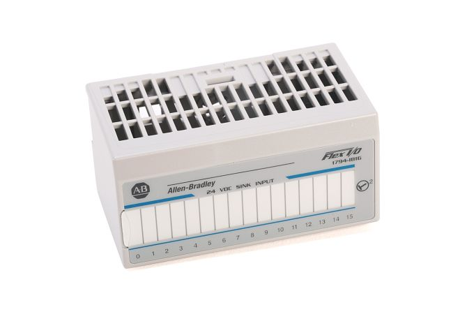
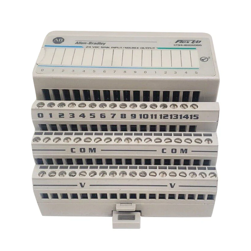
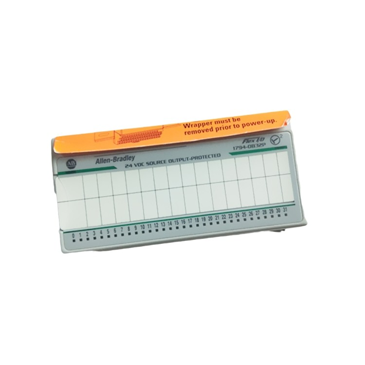
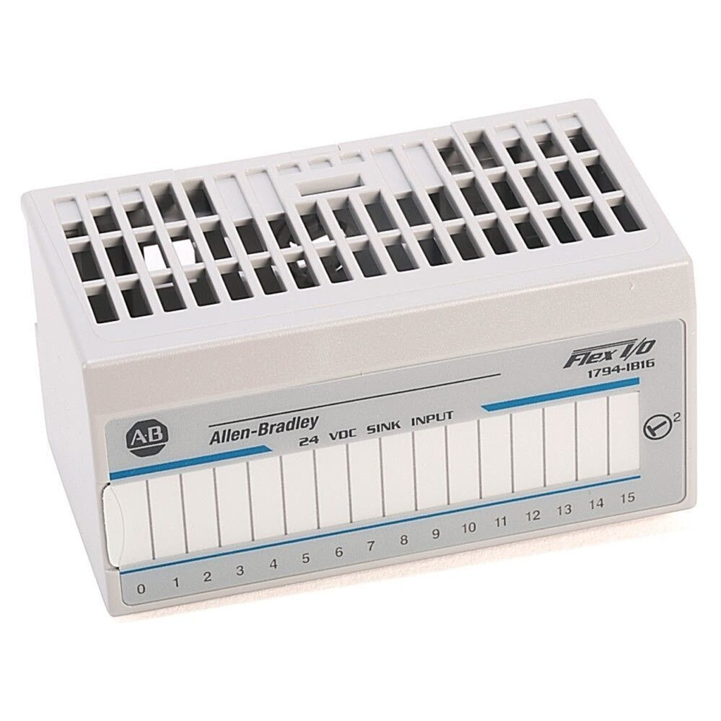
AB 1794-ID2 FLEX I/O 2-Channel Incremental Encoder Module

Safety and Use Precautions
Follow safety guidelines: Solid-state equipment has different operating characteristics than electromechanical equipment and should be used in accordance with the Safety Guidelines for the Application, Installation, and Maintenance of Solid-State Control Equipment (Publication SGI – 1.1) to ensure proper application of the equipment. Rockwell Automation is not responsible for consequential damages resulting from the use of the equipment. Manual examples are for reference only and may not be reproduced without permission.

Environmental and Installation Requirements: For use in industrial environments up to 2000 metres above sea level in Pollution Class 2, Overvoltage Category II, not for use in residential environments. To be installed in a suitable enclosure which is flame retardant and internally accessible only by means of tools. Use galvanised yellow chrome steel DIN rails for earthing, avoid corrosive, oxidised or poorly conductive rail materials, fix rails at 200mm intervals and use end anchors.

Electrostatic protection: The equipment is sensitive to static electricity and should be operated by touching an earthed object to discharge static electricity, wearing an earthed wrist strap, avoiding touching connectors and circuitry components, using an electrostatic safe workstation if available, and storing in electrostatic safe packaging when not in use.

Hazardous area use: There are specific approvals and requirements for use in Zone 2 in Europe and hazardous areas in North America. For example, for use in Europe, equipment must be protected against UV rays, enclosure protection levels, etc. For use in North America, products are labelled with a temperature code, and when combining equipment, the overall temperature code must be taken into account and reviewed by the local regulatory agency. When operating in hazardous areas, it is strictly prohibited to disconnect equipment or connections while energised to prevent the risk of explosion.

Module Installation
Mounting to Terminal Block: Mount the module to the 1794 – TB3 or 1794 – TB3S terminal block, turn the key switch to position 1 before mounting to ensure that the Flexbus connector is fully extended, insert the module into the groove with care and securely mount it to prevent debris from falling into the module, as an electrically charged plug or unplug may cause an explosion.
Wiring: Connect the input lines (A +, A -, B +, B -, Z +, Z -, G +, G -), the encoder common, the signal shield, the encoder power supply line, the +V DC power supply and the DC return to daisy-chain the power supply. The wiring method varies for different terminal blocks, so you need to refer to the corresponding tables and diagrams for operation.
Module Configuration: Configure the module functions by setting the control words, such as counting mode, preset function, calibration function, gate control function, memory control function, etc. Control words 0 and 1 are used to set the channel function, and control word 2 is used to set the filter function.

Specification
Basic parameters
Number of inputs and outputs: 2 input channels, 4 inputs (A, B, Z and G) for each counter.
Recommended terminal blocks: For 1794-TB3, 1794-TB3S, 1794-TBN, 1794-TBKD, 1794-TB37DS and others.
Key switch position: 1.
Enclosure type rating: None (open), meaning that it is used in an additional protective enclosure to meet the protection requirements of the specific application.
Electrical parameters
Input Characteristics: Input pulse width minimum 2μs to be recognised; maximum counting frequency 100kHz; on-state voltage min. 6V DC, max. 26.4V DC (24V DC +10%), current min. 3mA @ 6V DC, nominal 9mA @ 12V DC, max. 15mA @ 24V DC; off-state voltage min. 26.4V DC, max. 3V DC.
Isolation and Power Supply: Isolation voltage tested at 500V AC for 60s; FlexBus current 5mA @ 5V DC; Maximum power consumption 5W @ 26.4V DC, maximum thermal dissipation 17.1BTU/hr @ 26.4V DC; External power supply requirements 12 – 24V DC (+10%), supply current 150mA at 12V DC, 75mA at 24V DC. Power supply current is 150mA at 12V DC and 75mA at 24V DC.

Physical Parameters
Dimensions: Mounted dimensions are 46 x 94 x 53mm (1.8 x 3.7 x 2.1in.) for easy layout and installation in equipment.
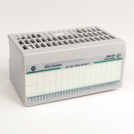
Indicators: 1 green/red power/status indicator and 12 yellow status indicators are provided to indicate the operating status of the module.
Conductors: Belden 8761 is recommended for input conductors up to 304.8m (1000ft.); wiring category 2 for planning conductor wiring.

Environmental parameters
Temperature Range: Operating temperature 0 – 55°C (32 – 131°F), but be careful not to connect the maximum input voltage to all inputs at the same time when the module ambient temperature is expected to exceed 40°C; Storage temperature – 40 – 85°C (-40 – 185°F).
Humidity and other: Relative humidity requirements are 5 – 95% non-condensing; capable of withstanding a certain level of vibration and shock, with vibration conditions of 5g @ 10 – 500Hz, 30g for operational shock, 50g for non-operational shock; in terms of EMC, conforms to the relevant standards, such as the Class A standard in CISPR 11 (IEC 61000-6-4) (with a suitable enclosure), and has a good understanding of the electrostatic discharge (ESD), radiated radio frequency (RF) (-40 – 185°F) and the electromagnetic compatibility (EMC). ESD, RF, EFT/B, surge transients and conducted RF.
Certifications: c-UL-us, CE, EAC, RCM, etc. certified. The c-UL-us certification indicates that the product complies with the U.S. and Canadian industrial control equipment standards and is suitable for use in hazardous locations; the CE certification complies with the relevant European Union EMC Directive; the EAC certification complies with the Russian Customs Union’s EMC technical regulations; the RCM certification complies with the Australian Radiocommunications Act, and the details of the certifications can be viewed through the product certification link.

AB 1794-IB10XOB6 FLEX I/O Digital Input/Output Modules

Safety and Use Precautions
Follow safety guidelines: Solid-state equipment has different operating characteristics than electromechanical equipment and should be used in accordance with the Safety Guidelines for the Application, Installation, and Maintenance of Solid-State Control Equipment (Publication SGI – 1.1) to ensure proper application of the equipment. Rockwell Automation is not responsible for consequential damages resulting from the use of the equipment. Manual examples are for reference only and may not be reproduced without permission.

Environmental and Installation Requirements: For use in industrial environments up to 2000 metres above sea level in Pollution Class 2, Overvoltage Category II, Group 1, Class A industrial equipment. To be installed in a suitable enclosure which is flame retardant and internally accessible only by means of tools. Use zinc-plated yellow chrome steel DIN rails for grounding, avoid corrosive, oxidised or electrically non-conductive rail materials.

Electrostatic protection: The equipment is sensitive to static electricity and should be operated by touching a grounded object to discharge static electricity, wearing a grounded wrist strap, avoiding touching connectors and circuitry assemblies, using a static-safe workstation when available, and storing in static-safe packaging when not in use.

Hazardous area use: There are specific approvals and requirements for use in Zone 2 in Europe and hazardous areas in North America. For example, for use in Europe, the equipment must be protected from UV rays and avoid open circuits on the secondary side of the current transformer; for use in North America, the product is labelled with a temperature code, and when combining the equipment, the overall temperature code must be taken into account and reviewed by the local regulatory agency. When operating in hazardous areas, it is strictly prohibited to disconnect equipment or connections while energised to prevent the risk of explosion.

Module Mounting
Mounting to Terminal Block: 1794 – IB10XOB6 modules are mounted to 1794 – TB3 or 1794 – TB3S terminal blocks, 1794 – IB16XOB16P modules are mounted to 1794 – TB32 or 1794 – TB32S terminal blocks. Ensure that the Flexbus connector is fully extended by rotating the key switch to position 2 before installation. Insert the module into the groove with care and install it securely to prevent debris from falling into the module, as an electrically charged insertion or removal could result in an explosion.
Wiring: The 1794-IB10XOB6 and 1794-IB16XOB16P modules are wired differently, so you need to follow the corresponding wiring diagrams to connect the input wires, output wires, power supply wires, and common wires, and you can daisy-chain the power supply.

Module Configuration: Configure the module by setting the bits in the configuration word (word 3), mainly to set the input filter time. The setting range of input filtering time is different for different modules, 0 – 9 for 1794 – IB10XOB6 and 0 – 15 for 1794 – IB16XOB16P, which corresponds to different filtering lengths, and can be adjusted according to the actual requirements.

Number and type of inputs and outputs
1794 – IB10XOB6: 10 inputs, current-flooding type; 6 outputs, current-pull type.
1794 – IB16XOB16P: 16 inputs, current-flooding type; 16 outputs, current-pull type.

Electrical Parameters
Input Characteristics
Voltage Range: The minimum on-state voltage of both modules is 10V DC, the nominal value is 24V DC, the maximum value is 31.2V DC, and the maximum off-state voltage is 5V DC.
Current Range: 1794 – IB10XOB6 input on-state current is 2.0mA minimum, 8.0mA nominal, and 11.0mA maximum; 1794 – IB16XOB16P input on-state current is 2.0mA minimum, 8.8mA nominal, and 12.1mA maximum; and the maximum value of both modules’ input off-state current is 1.5mA.
Input Impedance: The nominal input impedance of the 1794-IB10XOB6 is 4.8kΩ and that of the 1794-IB16XOB16P is 2.5kΩ.

Output Characteristics
Voltage Range: The output on-state voltage range is 10V DC minimum, 24V DC nominal, 31.2V DC maximum for the 1794-IB10XOB6, and the maximum for the 1794-IB16XOB16P as shown in the derating curve. Off-state voltage max. is 31.2V DC for all values.
Current range: 1794 – IB10XOB6 output on-state current per channel min. 1.0mA, max. 2.0A, total module current max. 10A; 1794 – IB16XOB16P output on-state current per channel min. 0.5A, max. 0.5A, total module current max. 8A.
Other parameters: 1794 – IB10XOB6 inrush current is 4A for 50ms, repeatable every 2s; 1794 – IB16XOB16P inrush current is 1.5A for 50ms, repeatable every 2s. The maximum off-state leakage current for both modules is 0.5mA. The maximum on-state voltage drop for the 1794-IB10XOB6 is 1V DC at 2A and 0.5V DC at 1A; the maximum on-state voltage drop for the 1794-IB16XOB16P is 0.5V DC at 1A.

AB 1794-IB8, -IB16, -IB16K FLEX I/O Digital Input Modules

Safety and Use Precautions
Follow Safety Guidelines: Solid-state equipment has different operating characteristics than electromechanical equipment and should be used in accordance with the Safety Guide for the Application, Installation, and Maintenance of Solid-State Controls, Publication SGI-1.1, to ensure proper application of the equipment. Rockwell Automation is not responsible for consequential damages resulting from the use of the equipment. Manual examples are for reference only and may not be reproduced without permission.

Environmental and Installation Requirements: For use in industrial environments up to 2000 metres above sea level in Pollution Class 2, Overvoltage Category II, Group 1, Class A industrial equipment. To be installed in a suitable enclosure, which should be flame retardant and internally accessible only by means of tools. Use zinc-plated yellow chrome steel DIN rails for grounding, avoid corrosive, oxidised or electrically non-conductive rail materials, fix the rails at 200mm intervals and use end anchors.
Electrostatic protection: The equipment is sensitive to static electricity. When operating, touch an earthed object to discharge static electricity, wear an earthed wrist strap, avoid touching connectors and circuitry assemblies, use an electrostatic safe workstation if available, and store the equipment in suitable electrostatic safe packaging when not in use.

Hazardous area use: There are specific approvals and requirements for use in Zone 2 in Europe and hazardous areas in North America, such as the need to install the equipment in an enclosure with at least IP54 protection for use in Europe, labelling of the product with a temperature code for use in North America, and consideration of the overall temperature code when combining the equipment and reviewing it with the local regulatory agency. Also, when operating in hazardous areas, it is strictly prohibited to disconnect equipment or connections while energised to prevent the risk of explosion.
Electrical Safety: To comply with the CE Low Voltage Directive (LVD), the equipment must be powered from a source that complies with Safety Extra Low Voltage (SELV) or Protection Extra Low Voltage (PELV).

Module Installation
Mounting to Terminal Block: Mount the module to the 1794 series terminal block, turn the key switch to position 2 before mounting to ensure that the Flexbus connector is fully extended, take care when inserting the module that it is aligned with the grooves and securely mounted to prevent debris from falling into the module, as an electrically charged insertion or removal could result in an explosion.
Wiring: 1794 – IB8, 1794 – IB16, and 1794 – IB16K are wired using 1794 – TB3 or 1794 – TB3S terminal blocks; 1794 – IB32 is wired using 1794 – TB32 or 1794 – TB32S terminal blocks. Connect the input, power and common wires according to the corresponding wiring table to daisy-chain the power supply.
Module Configuration: Configure the input module by setting the bits in the configuration word, mainly to set the input filter time. The setting range of input filter time is different for different modules, such as 0 – 7 for 1794 – IB8, 0 – 11 for 1794 – IB16 (12 – 15 for some of them), and 0 – 31 for 1794 – IB32, which corresponds to different filtering lengths, and can be adjusted according to the actual demand.

Specification
Input Characteristics
| Module Model | 1794 – IB8|1794 – IB16|1794 – IB16K|1794 – IB32
| – – – – – – – – – – – – – – – – – – –
| Number of inputs | 8 | 16 | 32 |
| Input Type | Non-Isolated, Current-Flooded | Non-Isolated, Current-Flooded | Non-Isolated, Non-Isolated in Group, Current-Flooded |
| Recommended Terminal Block | 1794 – TB3, 1794 – TB3S|1794 – TB3, 1794 – TB3S|1794 – TB32, 1794 – TB32S|
| On-state voltage (V DC)| Minimum 10, Nominal 24, Maximum 31.2 | Minimum 10, Nominal 24, Maximum 31.2 | Minimum 19.2, Nominal 24, Maximum 31.2|
| On-state current (mA)| 2.0 minimum, 8.0 nominal, 12.0 maximum | 2.0 minimum, 8.0 nominal, 12.0 maximum | 2.0 minimum, 4.1 nominal (at 24V DC), 6.0 maximum | Off-state voltage (VDC) | 10 minimum, 24 nominal, 31.2 maximum | 19.2 minimum, 24 nominal, 31.2 maximum
| Off-state voltage (V DC)| 5.0 max.
| Off-state current (mA)| 1.5 max.
| Input impedance (kΩ)|4.6|4.6|6.0|

Electrical Performance Parameters
Isolation Voltage: All 50V (continuous), basic insulation type, but with different test conditions. 1794 – IB8 tested at 850V DC for 60s, 1794 – IB16 and 1794 – IB16K tested at 707V DC for 60s, and 1794 – IB32 tested at 2121V DC for 2s with no isolation between individual channels of each module.
FlexBus Current: 20mA @ 5V DC for the 1794-IB8, 30mA @ 5V DC for the 1794-IB16 and 1794-IB16K, and 25mA @ 5V DC for the 1794-IB32, which is used to power the module’s FlexBus interfaces and to ensure that power is available for communication with other devices.
Power Consumption and Thermal Dissipation: 1794 – IB8 3.5W @ 31.2V DC and 11.9BTU/hr @ 31.2V DC; 1794 – IB16 and 1794 – IB16K 6.1W @ 31.2V DC and 20.8BTU/hr @ 31.2V DC; 1794 – IB32 6.0W @ 31.2V DC; 1794 – IB32 6.0W @ 31.2V DC. 6.0W @ 31.2V DC, maximum thermal dissipation 20.5BTU/hr @ 31.2V DC, reflecting the module’s energy consumption and heat dissipation during operation.

Physical Characteristics
Dimensions: The mounted dimensions are 94 x 94 x 69mm (3.7 x 3.7 x 2.7in.), allowing for easy installation in control cabinets and other equipment.
Indicators: The 1794-IB8 has 8 yellow status indicators, the 1794-IB16 and 1794-IB16K have 16 yellow status indicators, and the 1794-IB32 has 32 yellow status indicators to indicate the status of the input devices, allowing the user to monitor module operation.
Terminal Screw Torque: Determined by the mounted terminal block, it ensures firm wiring and avoids problems such as poor contact and unstable signal transmission due to loose screws.

AB 1794-IB8 FLEX I/O Digital Input Modules

IMPORTANT USER INFORMATION: Solid-state equipment has different characteristics than electromechanical equipment and should be used in accordance with applicable safety guidelines. Rockwell Automation is not responsible for consequential damages arising from the use of the equipment, and the manual examples are for reference only and may not be reproduced without permission. Includes a variety of safety tips, such as operating in hazardous environments, risk of electric shock and burns, and more.
Installation requirements: For use in industrial environments of pollution class 2, overvoltage category II, at altitudes up to 2000 metres above sea level, as Group 1, Class A industrial equipment. Installation in a specific enclosure that is flame retardant and accessible only by means of tools, with attention to electromagnetic compatibility.

Approval for use in hazardous areas
Europe: 1794 – IB8, 1794 – IB16 are approved for use in Zone 2 in Europe with additional requirements such as UV protection, enclosure protection level, avoidance of voltage overruns, etc.
North America: 1794 – IB8, 1794 – IB16, 1794 – IB32 approved for use in North American hazardous areas. Products are labelled with a temperature code, and when combining devices, attention should be paid to the overall temperature code and local regulatory review.

Installation Procedure
Installation to Terminal Block: Rotate key switch to ensure Flexbus connector is fully extended, align module with terminal block recesses, insert and securely install, taking care to prevent debris from falling into the module and possible hazards associated with energised plugs and unplugs.
Wiring: Use 1794-TB3 or 1794-TB3S terminal blocks for 1794-IB8 and 1794-IB16, and 1794-TB32 or 1794-TB32S terminal blocks for 1794-IB32 to connect the input wires, power wires, and common wires according to the corresponding wiring diagrams, respectively, and to daisy-chain the power supply.
Configure Input Module: Configure the input module by setting the bits in the configuration word, mainly to set the input filter time. The input filtering time setting range is different for different modules, such as 0 – 7 for 1794 – IB8, 0 – 11 for 1794 – IB16 (12 – 15 for some of them), and 0 – 31 for 1794 – IB32, which corresponds to different bit settings.

Input Characteristics
| Module Model | 1794 – IB8|1794 – IB16|1794 – IB32|
| Number of Inputs | 8-way | IB8 | 1794 – IB16 | 1794 – IB32 | 1794 – IB32
| Number of Inputs | 8 | 16 | 32 |
| Input Type | Current, Pour Current | Current, Pour Current | Current, Pour Current | Current, Pour Current | Current, Pour Current
| Recommended Terminal Blocks | 1794 – TB3, 1794 – TB3S, 1794 – TB3K, 1794 – TB3SK, 1794 – TBKD, 1794 – TB37DS|1794 – TB3, 1794 – TB3S, 1794 – TB3K, 1794 – TB3SK, 1794 – TBKD, 1794 – TB37DS |1794 – tb32, 1794 – tb32s, 1794 – tb62ds, 1794 – tb62exd4x15|, 1794 – tb62exd4x15
|On-state voltage (V DC)| Minimum 10, Nominal 24, Maximum 31.2 | Minimum 10, Nominal 24, Maximum 31.2 | Minimum 19.2, Nominal 24, Maximum 31.2 | On-state current (mc)
| On-state current (mA)| 2.0 minimum, 8.0 nominal, 12.0 maximum | 2.0 minimum, 8.0 nominal, 12.0 maximum | 2.0 minimum, 4.1 nominal (at 24V DC), 6.0 maximum | Off-state voltage (VDC) | 10 minimum, 24 nominal, 31.2 maximum | 19.2 minimum, 24 nominal, 31.2 maximum
| Off-state voltage (V DC)| 5.0 max.
| Off-state current (mA)| 1.5 max.
| Nominal Input Impedance (kΩ)|4.6|4.6|22.2

Electrical Performance Parameters
Isolation Voltage: All 50V (continuous), basic insulation type, but with different test conditions. 1794 – IB8 tested at 850V DC for 60s, 1794 – IB16 tested at 707V DC for 60s, and 1794 – IB32 tested at 2121V DC for 2s with no isolation between individual channels of each module.
FlexBus Current: 20mA @ 5V DC for the 1794 – IB8 and 30mA @ 5V DC for both the 1794 – IB16 and 1794 – IB32 is used to power the module’s FlexBus interfaces and to ensure that power is available for communication with other devices.

Power Consumption and Thermal Dissipation: 1794 – IB8 consumes 3.5W @ 31.2V DC with a maximum thermal dissipation of 11.9BTU/hr @ 31.2V DC; 1794 – IB16 consumes 6.1W @ 31.2V DC with a maximum thermal dissipation of 20.8BTU/hr @ 31.2V DC; 1794 – IB32 consumes 6.0W @ 31.2V DC with a maximum thermal dissipation of 20.0V DC; 1794 – IB32 consumes 6.0W @ 31.2V DC with a maximum thermal dissipation of 20.8BTU/hr. DC, maximum thermal dissipation 20.47BTU/hr @ 31.2V DC , reflecting the module’s energy consumption and heat dissipation during operation.
Physical specification parameters: the document does not explicitly mention the module size, weight and other specific physical dimensions of the parameters, but mentioned that the type of enclosure is none (open), the protection performance is dependent on the installation of the shell to achieve, and gives the conductor category of the signal port 2, used to guide the wiring planning.

Environmental suitability parameters
Temperature range: – 20…55°C (-4…131°C) for the 1794-IB8 and 1794-IB16, 0…55°C (32…131°F) for the 1794-IB32; storage temperature are – 40…85°C (-40…185°F), reflecting the range of operating and storage temperatures tolerated by the different modules.

Humidity and others: Relative humidity requirements are 5…95% non-condensing; for vibration, 5g @ 10 – 500Hz during operation; for shock, 30g during operation and 50g during non-operation, demonstrating the modules’ ability to adapt to different environmental conditions.
Electromagnetic compatibility: comply with CISPR 11 Group 1, Class A standard (need to be suitable for the shell), with a certain degree of immunity to electrostatic discharge (ESD), radiated radio frequency (RF), electrical fast transient pulse group (EFT/B), surge transients and conducted radio frequency, etc., but there are differences in the specific frequency range of the immunity of different modules in the radiated RF, to ensure the stability of operation in the complex electromagnetic environment. operation in complex electromagnetic environments.

Certification parameters: Passed c-UL-us, CSA, CE and many other certifications, and the details of different module certifications are different. Such as c-UL-us certification indicates that the product meets the U.S. and Canadian industrial control equipment standards and is suitable for hazardous locations; CSA certification involves process control equipment and hazardous locations; CE certification in line with the relevant European Union EMC Directive, you can check the details of the certification information through the website.

AB 1794 – AENT Series B FLEX I/O EtherNet/IP Adapter

Installation requirements: The equipment is suitable for use in industrial environments of pollution class 2, overvoltage category II, at altitudes up to 2000 metres above sea level, and is classified as Group 1, Class A industrial equipment. It is to be installed in a suitably designed enclosure that is flame retardant and the interior can only be accessed by means of tools.

Installation steps
Mounting to DIN rail: Hook the rear of the adapter onto the top of the 35 x 7.5 mm DIN rail, rotate and press it against the rail, if not locked it can be done with a tool.
Replacing the adapter in an existing system: Remove the relevant connections in turn, take care to align the slots when installing the new adapter, and reconnect the wiring once the installation is complete.

Wiring Methods
Network cable connection: Connect the Ethernet network cable to the RJ45 connector on the bottom of the adapter, it is recommended to connect it through a 100 MB full duplex switch.
Power Connection: 24V common is connected to the left terminal B of the upper connector, +24V dc input power is connected to the left terminal C of the lower connector, and power can be supplied to the subsequent modules through connectors D and E. No more than 2 wires should be connected to a single terminal, and the terminal screws should be torqued to 0.8 Nm (7 lb – in) when connecting.
Network Address Settings: The adapter is shipped from the factory with the jog wheel switch set to 999 and DHCP enabled, allowing you to obtain an IP address using the jog wheel switches (001 – 254), a DHCP server, or from non-volatile memory. A switch value of 888 resets all configuration parameters to factory settings.

Indicator Status Interpretation: 1794 – The AENT adapter has three two-colour indicators on the front panel, the Module Status Indicator, the Network Status Indicator, and the Link Status Indicator, with different blinking or always-on statuses representing different operating states.
Environmental specifications: Operating temperature 0 – 55°C (32 – 131°F), non-operating temperature – 40 – 85°C (-40 – 185°F), relative humidity 5 – 95% non-condensing, able to withstand a certain degree of vibration and shock, in the electromagnetic compatibility requirements.

Specification
Electrical Parameters
Power Requirements: To comply with the CE Low Voltage Directive (LVD), the unit needs to be powered by a Safety Extra Low Voltage (SELV) or Protection Extra Low Voltage (PELV) compliant power supply. The input voltage is rated at 24V dc nom, and the input voltage range is 19.2-31.2V dc (including 5% AC ripple), which can adapt to a certain range of voltage fluctuations and ensure stable operation under different power conditions.
Communication rate: It supports 10/100 Mbps communication rate, which can be negotiated automatically according to the network environment and equipment requirements to meet the data transmission speed requirements in industrial automation scenarios and ensure fast and stable data transmission.

Current and Power: The maximum output current of Flexbus is 640 mA, which can provide stable power support for the connected I/O modules. In terms of power consumption, the maximum is 550 mA and 440 mA at 24V dc; the power dissipation is 7.3 W at 19.2V dc and the heat dissipation is 24.9 BTU/hr at 19.2V dc, which reflects the energy consumption and heat dissipation of the device during operation.
Isolation Voltage: 50V continuous isolation voltage, which belongs to the basic insulation type and has been tested by 1000V ac for 60s (between power supply and Flexbus, EtherNet), effectively isolating different circuits and enhancing the safety and anti-interference ability of the equipment.
Mechanical Parameters
I/O capacity: I/O capacity is 8 modules, which specifies the upper limit of the number of FLEX I/O modules that can be connected to the adapter, and the number of I/O points and the scale of equipment connection should be planned accordingly in the system design.
Connector Type: The Ethernet connector adopts the RJ45 Cat. 5 standard interface, which is widely used for Ethernet connection with good versatility and stability, and is convenient to connect with other network devices.

Terminal Screw Torque: The terminal screw torque is required to be 0.8 Nm (7 lb – in), which ensures firm wiring and avoids problems such as poor contact and unstable signal transmission caused by loose screws.
Wire Specifications: Power conductors are 0.34 – 2.5 mm² (22 – 12 AWG) stranded copper wire rated at 75°C (167°F) or higher, with a maximum insulation thickness of 1.2 mm (3/64 in.) to meet electrical performance and safety requirements. Conductors are classified as Class 1 for power ports and Class 2 for communication ports to provide guidance for wiring planning.

Environmental Parameters
Temperature range: Operating temperature range is 0 – 55°C (32 – 131°F), non-operating temperature range is – 40 – 85°C (-40 – 185°F), can adapt to a variety of industrial environment temperature changes, in different seasons and working scenarios to maintain stable performance.
Humidity Requirements: Relative humidity range of 5 – 95% and non-condensing, can work normally in a certain humidity environment, to avoid humidity problems affecting the electrical performance and service life of the equipment.

Vibration and shock: able to withstand a certain degree of vibration and shock, working vibration conditions for 5 g @ 10 – 500 Hz, working shock for 30 g, non-working shock for 50 g, to adapt to the vibration and shock environment of the industrial site, to ensure the reliability of equipment operation.
Electromagnetic compatibility: Strict requirements in electromagnetic compatibility, such as compliance with CISPR 11 Group 1, Class A standards, electrostatic discharge (ESD), radiation radio frequency (RF), electric fast transient pulse group (EFT/B), surge transients, etc. have a certain immunity, reduce the impact of electromagnetic interference on the equipment, to ensure stable operation in a complex electromagnetic environment.

Other parameters
Enclosure type rating: Enclosure type rating for no (open), meaning that it needs to be installed in a suitable protective enclosure to adapt to the specific use of the environment, such as dust-proof, waterproof, anti-electromagnetic interference and so on.
North American temperature code: North American temperature code is T4A, which indicates the temperature limit and safety level when the equipment is used in hazardous places in North America, and helps users to choose the right equipment in a specific area and ensure safe use.

AB 1794-ACNR FLEX I/O ControlNet Redundant MediaAdapter

Component Description: Describes in detail the components of the adapter, including the ControlNet adapter module, indicator lights, ControlNet network cable BNC connectors (3a, 3b, 3b 1794-ACNR15 only), ControlNet node selector jog wheel switch, programming terminal connector port, module locking tab, +24V dc connector, 24V common connector, and Flexbus connector, clarifying the location and basic function of each component in the device.

Mounting Procedure
Mounting to DIN rail: Place the adapter module on the 35 x 7.5mm DIN rail at an angle, hang the hook on the back of the adapter and rotate it onto the rail, press it against the rail and the locking tab will automatically snap into place. If it does not lock properly, use a screwdriver or other tool to press down on the locking tab and operate the adapter until it locks, and then proceed with wiring.
Note: When installing the adapter, make sure that the hooks on the terminal block are correctly hooked into the adapter, otherwise backplane communication may be interrupted.

Interpretation of Status Indicators: The indicators provide a visual indication of the operating status of the adapter. For example, if Comm A and Comm B are off at the same time, it may indicate that there is no power supply or it is in the reset state; if they show red colour at the same time, it means that the adapter is not working; if they flash red/green alternately, it means that the adapter is performing self-test; if they flash red/black alternately, it may mean that the node is mis-configured (the address is duplicated). Comm A or Comm B display different status individually, such as off means the channel is disabled, green means the channel is running normally, etc. There are also other status indicators corresponding to different statuses such as online but not connected, connected normally, recoverable fault, adapter failure, etc.

Specification
Electrical Parameters: Input voltage range is 19.2V to 31.2V dc (with 5% AC ripple) and communication rate is up to 5M Bits/s. Current consumption is 640mA at 5V dc and 400mA from external 24V power supply; maximum power consumption is 4.6W at 19.2V dc and thermal dissipation is 15.7 BTU/hr.
Environmental parameters: Operating temperature range is 0 to 55°C (32 to 131°F), non-operating temperature range is -40 to 85°C (-40 to 185°F), and relative humidity is 5% to 95% non-condensing. In terms of shock and vibration, it can withstand 30g peak acceleration, 11 (+1) ms pulse width in operation, 50g peak acceleration, 11 (+1) ms pulse width in non-operation, and has been tested to withstand vibration of 5g @ 10 – 500Hz (in accordance with IEC 68 – 2 – 6).
Other parameters: I/O capacity for connecting 8 modules, cable for Belden RG-6/U, 12 gauge (4mm²) stranded wire, maximum insulation thickness 3/64 inch (1.2mm), terminal screw torque requirement 7-9 in-lb.
Approval information: The adapter is certified by several authorities, such as CSA certification, CSA Class I, Division 2 Groups A, B, C, D, UL listing and CE marking (in accordance with all applicable directives), which indicates that the product meets the relevant safety and quality standards and is legal for sale and use in the respective markets.

Performance characteristics
Communication Performance
High-speed communication: Supporting a communication rate of 5M Bits/s, it can achieve high-speed data transmission in ControlNet network to meet industrial automation scenarios requiring high real-time performance, such as data interaction and cooperative control between a large number of devices in industrial production lines, to ensure fast and accurate data transmission and to reduce the delay in system response.
Redundant design: Equipped with two ControlNet network cable BNC connectors (3a and 3b, model 1794 – ACNR15), with communication redundancy function. When one communication link fails, it automatically switches to the other, guaranteeing communication continuity, increasing system reliability and reducing the risk of production downtime due to communication interruptions.

Adaptability
I/O module connection: The I/O capacity is 8 modules, which can connect various types of FLEX I/O modules, such as digital, analogue, thermocouple and RTD modules, to meet the diversified needs of different industrial equipment for the number and type of I/O points, and facilitate the construction of complex automation control systems.
Network Adaptation: It can be used as a node of ControlNet network, and the address setting can be done through the node selection dial switch, which can be well adapted with other ControlNet network devices to achieve interconnection and intercommunication among devices, and flexible networking in the industrial network architecture.

Stability
Wide voltage range: The operating voltage range is from 19.2V to 31.2V dc (including 5% AC ripple), which is highly adaptable to the power supply and can operate stably under different power supply conditions, reducing equipment failures due to power supply fluctuations and ensuring normal operation in complex industrial power supply environments.
Environmental Adaptability: Operating temperature range of 0 to 55°C (32 to 131°F), non-operating temperature range of -40 to 85°C (-40 to 185°F), relative humidity of 5% to 95% non-condensing, and withstand a certain degree of shock and vibration (operating 30g peak acceleration, 11 (+1) ms pulse width, non-operating 50g peak acceleration, 11 (+1) ms pulse width, 5g @ 10g). ms pulse width, 5g @ 10 – 500Hz vibration), and can withstand a wide range of industrial environments, from hot steel production plants to humid chemical sites.

AB Bulletin 1794 and 1797 LEX I/O and FLEX Ex I/O Systems

FLEX I/O System
System Overview: Connects to a wide range of networks and features a modular design for high flexibility and low cost for distributed applications. Up to eight I/O modules can be connected to a single adapter, supporting a wide range of I/O point combinations.Designed for extreme environments, the FLEX I/O XT is coated for protection, meets many standards, and is resistant to a wide range of reactive substances.

Module Options
Digital I/O modules: Covering a wide range of electrical ranges such as 120V AC, 220V AC, 24V DC, etc., available in different densities from 8 to 32 points. Features isolation, protection, diagnostics, optional input filtering time, and LED status indication for each channel.
Analogue, thermocouple and RTD modules: channels can be individually configured, support online configuration, selectable input filters, etc., capable of controlling the operation of output devices under abnormal conditions, different modules have different accuracy and resolution.
Counter modules: Selected according to the type of application and field equipment, such as 1794 – IJ2XT for proportional control, 1794 – VHS for packaging, material handling, etc.
System mounting and accessories: Panel or DIN rail mounting, with grounding, using DIN rails made of zinc-plated yellow chrome steel. A wide range of accessories are available, such as extension cables, mounting kits, DIN rail latches, etc., and comprehensive documentation is also available.

FLEX Ex I/O System
System overview: Intrinsically safe for use in hazardous areas, eliminating the need for explosion-proof enclosures and additional intrinsically safe isolation components. Based on a physical architecture, categorised by hazardous area designation, connectable to a wide range of networks, modules can be plugged and unplugged electrically and have a wide range of protection features.

Module Options
Digital I/O modules: Fault detection, indication and reporting, selectable input filter time, LED status indication for each channel.
Analogue module: channel configurable, with on-board calibration, online configuration, etc., can detect over-range and under-range, and can control the operation of output devices under abnormal conditions.
Counter I/O Module: Suitable for applications such as tacho control, reports frequency, acceleration and direction, and receives and returns binary data.

System Installation and Power Supply Selection: Requires selection of the appropriate adapter and distribution method, with a variety of adapters available. Power supplies are available in N-type (vandal-proof) and E-type (fire-proof) housings, complying with North American and European standards, respectively, and offering different input voltages. The number of power supplies and their distribution need to be determined according to system planning. Documentation is available to support this.

AB FLEX I/O Remote I/O Adapter Module

Safety and Usage Precautions
Prohibited Scenarios: Do not use with Classic PLC-5/15 or PLC-5/25 processors.
Safety Guidelines: Solid-state devices have different characteristics than electromechanical devices and should be used in accordance with applicable safety guidelines; Rockwell Automation is not responsible for consequential damages.
Environmental Requirements: Suitable for use in pollution class 2, overvoltage category II industrial environments at altitudes up to 2000 metres above sea level, Group 1, Class A industrial equipment, and in a suitable enclosure.
Static electricity protection: The equipment is sensitive to static electricity, anti-static measures are required during operation.

Other notes: There are strict requirements on the length of power supply wiring, grounding methods, preventing the entry of foreign objects, and avoiding electrically charged operation.
Approval for use in hazardous areas
Europe: The modules are approved for use in Zone 2 in Europe and are subject to specific requirements, such as UV protection and enclosure protection.
North America: Modules are approved for use in hazardous areas in North America, with product labelling ‘CL I, DIV 2, GP A, B, C, D’, and use is subject to temperature codes and combined equipment review.
Installation Steps
Pre-installation Preparation: Clearly identify components and understand standard addressing modes and substitution relationships.

Mounting to DIN rail: Hook adapter onto DIN rail and rotate down to ensure it locks into place, if not it can be done with a tool.
Replacement in an existing system: Remove the relevant parts in order, take care to align the slots when installing the new adapter, and reconnect the wiring when the installation is complete.
Wiring: Connect the remote I/O cable, power supply, pay attention to the location and order of wiring, if the last adapter needs to be terminated resistor.
Addressing mode setting: Select the addressing mode by setting S1 and S2 switches, different modes correspond to different switch settings, and need to re-power on after setting.

Practical Application Cases
Automobile production line: In the automobile production workshop, a large number of equipments need to be monitored and controlled in real time. For example, in the body welding process, many welding robots and sensors need to communicate with the control system. FLEX I/O Remote I/O Adapter Module can connect the digital input and output signals of the robot, such as controlling the start and stop of the welding gun, and monitoring the analogue signals of the welding current and voltage sensors.

With its multiple addressing modes, it can be flexibly configured to address different devices and transmit data stably to the main control system via 57.6Kbps, 115.2Kbps or 230.4Kbps communication rates, ensuring that the welding work is carried out accurately and improving production efficiency and product quality.

Chemical production process control: The chemical production environment is complex, with corrosive gases and potential explosion risks. For example, the 1794 – ASBK series E module (for hazardous gas environments) can be used for liquid material transport and reaction control. It connects flow sensors, pressure sensors to monitor the material flow, reactor pressure and other analogue signals, as well as digital signals to control the opening and closing of valves. By communicating with the control system, it regulates the production process according to the set parameters. Module grounding and protection design, with explosion-proof shell, can ensure stable operation in chemical hazardous environments and prevent safety accidents caused by electrostatic discharge and electrical failure.

Intelligent warehousing and logistics systems: In automated three-dimensional warehouses, shuttle cars, stacker cranes, and other equipment need to be controlled precisely, and the FLEX I/O remote I/O adapter module connects the equipment’s motor drives, position sensors, etc. The module can, for example, be used to monitor the position of a stacker crane. For example, the digital signals from the position sensors of the stacker cranes are monitored to determine their position between shelves, and the module’s communication function transmits the position information to the control system, which then controls the movement of the stacker cranes accordingly. Its flexible installation method and various wiring specifications facilitate installation and connection in the complex wiring environment of storage equipment to achieve efficient cargo storage and retrieval.

Parameter specifications
I/O Capacity: The I/O capacity of 1794-ASB/E and 1794-ASBK/E is 8 modules, while 1794-ASB2/D is 2 modules. This determines the number of FLEX I/O modules that can be connected to them. In industrial automation projects of different sizes, the appropriate model can be selected according to the actual equipment connection requirements. For example, for a small production line with relatively few devices, the 1794-ASB2/D may be able to meet the connection requirements, while a complex production line in a large factory involving the monitoring and control of many devices may require a module with a larger I/O capacity such as the 1794-ASB/E.

Power Requirements: All models require a power supply capable of delivering 23A (24V DC) with a 2ms start-up inrush current. The input voltage range is 19.2V…31.2V DC, within which the module can operate stably. Taking 1794-ASB/E as an example, the module can still work when the connected power supply voltage is at the lower limit of 19.2V, but if the voltage is continuously lower than this value, the performance may be unstable or even unable to work normally; if the voltage is higher than 31.2V, it may cause damage to the internal circuitry of the module. The output voltage is 5V DC, 640mA, which can provide stable working voltage for the connected FLEX I/O modules.

Communication Rate: 1794-ASB/E, 1794-ASBK/E and 1794-ASB2/D support three communication rates: 57.6Kbps, 115.2Kbps and 230.4Kbps. Users can flexibly choose the appropriate communication rate according to the requirements of real-time data transmission and the quality of the communication line in the actual application scenarios. For example, in the environment of low real-time data transmission requirements and certain interference in the communication line, the rate of 57.6Kbps can be selected to ensure the stability of data transmission; while in the very high real-time requirements, such as some high-speed operation of the equipment monitoring scenarios, you can choose the high speed rate of 230.4Kbps, to ensure that the data is transmitted in a timely and accurate manner.

Indicator Lights: All of them are equipped with power (green), adapter activity (green), adapter failure (red), local failure (red) indicator lights. These indicators provide visual feedback on the module’s operating status. When the power indicator lights up green, it indicates that the module has been connected to a normal power supply; the adapter activity indicator flashes green, indicating that the module is carrying out normal data communication activities; if the adapter failure indicator turns red, it means that the module may have internal faults that need to be investigated in a timely manner; and the local fault indicator turns red, suggesting that there may be a problem with the locally-connected device or line.

Dimensions: Dimensions (H x W x D) are 87 x 69 x 69mm (3.4 x 2.7 x 2.7 inches), the compact size makes it easier to install and arrange in control cabinets and other space-limited environments, space-saving, and easy to integrate with other equipment.
Isolation Voltage: Isolation voltage is 50V (continuous), basic insulation type, tested at 750V DC for 60s (between power supply and system, power supply and RIO, RIO and system). This electrical isolation design effectively prevents electrical interference between different circuits, protects the module and connected devices from electrical shocks and interference, improves the stability and reliability of system operation, and ensures safe operation in complex industrial electrical environments.

AB 1786 – RPA/B ControlNet Modular Repeater Adapter

Product Summary: The 1786 – RPA/B Repeater Adapter with specific modules builds repeaters for ControlNet networks, extending the network, switching topologies and media, and connecting up to 20 in series.
IMPORTANT: Unlike electromechanical devices, solid-state devices should be used in a manner that ensures proper application and Rockwell Automation is not responsible for consequential damages. Examples in this document are for illustrative purposes only and may not be reproduced without permission. Various safety warnings are given, such as operating in hazardous environments, protection against static electricity, and other precautions.

Environmental and Installation Requirements
Environmental conditions: Suitable for use in industrial environments with pollution level 2, overvoltage category II, at altitudes up to 2000 metres above sea level, Group 1, Class A industrial equipment, to be installed in a suitable enclosure.
Hazardous Location Use: For North American hazardous locations, products labelled ‘CL I, DIV 2, GP A, B, C, D’ have specific temperature code requirements; for European Zone 2 environments, equipment must be mounted in an enclosure with at least IP54 protection.
Static electricity protection: The device is sensitive to static electricity and should be operated in accordance with protective measures such as touching grounded objects, wearing a wrist strap, etc.

Module mounting
Mounting preparation: Horizontal mounting is recommended, vertical mounting is also possible (top mounting is recommended), using DIN rails made of zinc-plated yellow chromate steel and properly grounded.
Mounting procedure: Hang the module on the DIN rail at an angle of 30° and rotate it to snap into place, mount the repeater module, secure it with the DIN rail lock, make sure that the total number of modules and the power consumption do not exceed the limits, tighten the screws to 1.1 N・m.
Module wiring: Disconnect the power when wiring, prepare tools and wires, connect the wires to the V in+ and V in terminals of the RTBs after stripping, tighten the screws to 0.6 – 0.8 N・m, install the RTBs and connect them to the ControlNet network, connect the unused ports with a 75Ω terminator.
Status indicators: The status indicators are available in different combinations to indicate different states. For example, alternating red/green indicates that the module is powered up or reset; solid red indicates that a node is continuously transmitting on the network; and off indicates unpowered or faulty.

Technical Specifications
Electrical Specifications
Power Consumption and Power Dissipation: Maximum power consumption is 16.8 W and maximum power dissipation is 8.8 W. These two parameters reflect the energy consumption and heat dissipation requirements of the device during operation, which is of great significance to the power configuration and heat dissipation design of the system. In practice, it is necessary to ensure that the power supply can provide sufficient power, and at the same time to consider the heat dissipation measures of the equipment to ensure its stable operation.

Input Voltage: The input voltage is rated at 700mA @ 24V DC, which is classified as Class 2/SELV (Safety Extra Low Voltage). The input voltage range is 18 – 36V DC, which means that the device can operate normally within a certain voltage fluctuation range, but exceeding this range may affect the performance of the device or even cause damage. When selecting a power supply, it is important to ensure that the output voltage meets the requirements of the device.

Backplane Output Current: The maximum backplane output current is 1.6A @ 5V DC, which limits the total current consumption of other devices connected to the backplane. When designing a system, it is necessary to consider the power consumption of the connected devices to avoid exceeding the limit of the backplane output current, which may lead to device failure or unstable operation.

Mechanical specifications: The minimum enclosure dimensions are approximately (12 x 7.75 x 4 in.) i.e. 304.8 x 196.8 x 101.6 mm, which specifies the space occupation of the device, and when installing the device, it is necessary to make sure that there is enough space to accommodate the device. There is no restriction on the mounting direction of the device, and the appropriate mounting method can be selected according to the actual situation, but horizontal mounting is preferred, and it is recommended that the device be mounted on the top when installed vertically.

Environmental specifications
Temperature: The maximum ambient air temperature is 140°F (60°C), which limits the ambient temperature range in which the unit can be used. When used in a high temperature environment, care should be taken to dissipate heat to prevent damage to the unit due to overheating. If the ambient temperature exceeds the equipment’s tolerance range, it may result in reduced performance, shortened life, or even failure.

Vibration and Shock: In terms of vibration, the device complies with IEC60068 – 2 – 6 (Test Fc, Operating) and can withstand vibration of 5 g @ 10 – 500 Hz; in terms of shock, the device complies with IEC60068 – 2 – 27 (Test Ea, Unpackaged Shock) and can withstand shock of 30 g. These parameters indicate that the device can withstand a certain level of vibration and can withstand a shock of 30 g. The device can withstand a shock of 30 g if the ambient temperature exceeds the range. These parameters indicate that the equipment can maintain normal operation in a certain vibration and shock environment, but in practice, the equipment should try to avoid excessive vibration and shock.

Electromagnetic compatibility: It has certain electromagnetic compatibility, such as ESD (electrostatic discharge) immunity of 6 kV contact discharge and 8 kV air discharge; Radiated RF immunity has different requirements in different frequency ranges, such as 10V/m with 1 kHz sine – wave 80% AM from 80 – 2000 MHz, etc; EFT/B immunity is ±4 kV at 5 kHz at power and communication ports; Surge transient immunity has different tolerance values at different ports, e.g. ±1 kV line – line (DM) and ±2 kV line – earth (CM) at power port, etc.; Conducted RF Immunity is 10V rms with 1 kHz sine-wave 80% AM from 150 kHz – 80 MHz. These parameters ensure that the device can work properly in complex electromagnetic environments without causing interference to other devices.

Approvals: Several approvals have been obtained, including UL (UL Listed Industrial Control Equipment), CSA (CSA Certified Process Control Equipment, etc.), FM (FM Approved Equipment for use in), FM (FM Approved Equipment for use in), and FM (FM Approved Equipment for use in). FM (FM Approved Equipment for use in Class I Division 2 Group A,B,C,D Hazardous Locations), CE (European Union 2004/108/EC EMC Directive etc.), C-Tick (Australian Radiocommunications Act), Ex (European Union 94/9/EC ATEX Directive) and CI (ControlNet Int’l conformance tested to ControlNet specifications). These certifications indicate that the equipment complies with relevant safety, quality and industry standards and is safe for use in the respective regions and environments.

AB 1785 um019 PLC-5 Ethernet Interface Module

Specification Technical Parameters
Electrical Characteristics
Backplane current: The backplane current is 2.2A, which determines the amount of current that the module receives from the backplane during operation and affects the power distribution and stability of the whole system. When designing the power supply system, it is necessary to ensure that the backplane can provide sufficient current to meet the normal operation requirements of the module and other equipment.
Heat dissipation: The heat dissipation is 37.54 BTU/hr, indicating that the module generates a certain amount of heat during operation and requires reasonable heat dissipation measures to ensure its stable operation. If the heat dissipation is not proper, it may cause the module temperature to be too high, affecting its performance and life.

Environmental Adaptability
Temperature range: 0 to 60°C (32-140°F) for operation and – 40 to 85°C (- 40 to 185°F) for storage. This allows the module to operate and be stored in a range of temperatures, but additional temperature regulation should be considered when using the module in extreme temperature environments.
Humidity Requirements: Relative humidity of 5 to 95% (non-condensing) indicates that the module can tolerate a certain range of humidity, but high humidity and condensing environments should be avoided to prevent electrical short circuits and other failures.

Mechanical properties
Shock resistance: 30g peak acceleration during operation, duration 11 ± 1ms; 50g peak acceleration during non-operation, duration 11 ± 1ms, which indicates that the module has a certain degree of shock resistance in the transport and use of the process, but in the actual application of the need to avoid a strong shock, so as not to damage the internal components.
Vibration Resistance: Withstands 2g of vibration with a peak-to-peak displacement of 0.012’ over a frequency range of 10 to 500Hz. This feature ensures that the module can work stably in industrial environments where vibration is present and reduces the risk of loosening connections or damaging components due to vibration.

Communication Capabilities
Communication protocols and ports: Ethernet (TCP/IP protocol) is used for communication, and the 15-pin AUI transceiver port connects to the network, ensuring compatibility with Ethernet devices and stability of data transmission.
Number of Connections: Supports 64 simultaneous connections, which can meet the needs of simultaneous communication of multiple devices. This parameter is very important for systems that require data interaction with multiple end devices, which determines the communication capacity and scalability of the system. The module also supports 512 unsolicited definitions (for the RSLinx and INTERCHANGE packages), which further enhances its communication capabilities in specific software environments.

Installation
Mounting Location: Mounted in the second left slot of the 1771-A1B, -A2B, -A3B, -A3B1, -A4B chassis and connected to the processor, the clear mounting location requirement helps to ensure that the module is installed correctly and operates correctly in the system.
Weight: 0.95 kg (2.1 lbs), a parameter that needs to be taken into account when designing the overall layout and mounting of the unit, especially for applications with stringent weight requirements.
Approvals: CSA Class I, Division 2, Groups A, B, C, D certification, UL listing and CE marking (for all relevant directives) signify that the module meets the relevant safety and quality standards and is safe for use in the respective area.

Module installation
Preparation for installation: Use specific programming software and corresponding processor, check the module packaging, record the Ethernet hardware address, prepare installation tools and equipment, and take precautions against static electricity.
Installation Procedure: Connect the connector plug to the processor, connect the interface module to the processor, and install the combo module into the leftmost slot of the 1771 I/O chassis. Installation requires attention to pin alignment and power down.
Removing the Module: To remove the module, disconnect the power, lift the locking lever and eject the tabs, and loosen the screws to separate the module.

Module Configuration
Configuration preparation: Each Ethernet hardware address should be assigned a unique IP address, which can be set manually or through the BOOTP protocol.
Configuration operation: Use programming software to specify the channel 3A support module, disable BOOTP, set diagnostic files, IP address and other parameters when configuring manually; when using BOOTP, you need to have a server and edit the BOOTPTAB file.

Communication Operation
Status monitoring: Judge the operation status of the module through the LED indicator after power on, the status indicator is always green when it is normal, and the transmission indicator turns green briefly when it is transmitting.
Connection Establishment: After establishing Ethernet connection, you can monitor the communication status data through the diagnostic file, including the sending and receiving of commands, replies, data packets, etc. and the error situation.
Data transmission: Use the MSG instruction to transmit data, note that the control block address should be even, set the command parameters, and set the port number to 3A when communicating through the Ethernet interface module.

Search for products

Back to Top
Product has been added to your cart