The Brand Rolls-Royce is an exemplar of high-end global manufacturing, renowned not only for its luxury and performance in the automotive sector, but also for its advanced engine technology in the aerospace industry, and for its marine equipment. As a global leader in marine design, propulsion, engineering, hydrodynamics and systems integration, Rolls-Royce has equipped more than 20,000 commercial and naval vessels, and its products and systems are widely used in the maritime market. With profound technology accumulation, strict quality control and continuous innovation, Rolls-Royce marine controllers are trusted by global shipping enterprises and ship manufacturers, and H1111.0104 marine controller is the strong testimony of its brand’s excellent quality.
Specification Although the detailed official parameters of H1111.0104 marine controller are not available for the time being, it can be reasonably presumed by referring to the models of H1111.0102 and H1111.0204 of the same series. For example, the H1111.0102 has an operating frequency of H6029/300MHz and weighs about 2.040kg, part number 75669; the H1111.0204 model (part number 75670) has an operating frequency of H6036/1.0GHz. It is inferred that H1111.0104 may have similar communication frequency settings precisely adapted to the ship’s complex electromagnetic environment, ensuring stable and high-speed data transmission and command interaction with various ship equipment, and guaranteeing smooth operation of the ship control system. In terms of weight and size, the limited installation space and load limitations of the ship will be fully considered, designed to be compact and lightweight, while ensuring a durable structure that can adapt to the ship’s bumpy, vibrating operating environment.
Performance Advantages High Reliability: High probability of using high-strength, corrosion-resistant special alloys to create the shell, effectively resisting seawater erosion, salt spray corrosion and humid air, to prevent rust and deformation of the shell, to provide reliable physical protection for the internal precision electronic components. The internal circuitry is strengthened by advanced potting technology and reinforcement treatment to enhance vibration and shock resistance, reduce the probability of failure due to the ship’s rocking and bumps during navigation, and ensure long-term stable operation in harsh marine
environments. Precise control: It is very likely to be built-in advanced and complex control algorithms, which can quickly and accurately calculate the optimal control parameters for each equipment of the ship based on the real-time running status of the ship, feedback data from various high-precision sensors (e.g., rotational speed sensors, pressure sensors, position sensors, etc.) and instructions from the operator. Whether it is precisely adjusting the engine speed to match different sailing speeds, loads and sea conditions, or accurately controlling the steering angle of the rudder to achieve smooth steering of the ship, all of them can be carried out with extremely high precision to ensure that the ship maintains the best operating state under various complex working conditions.
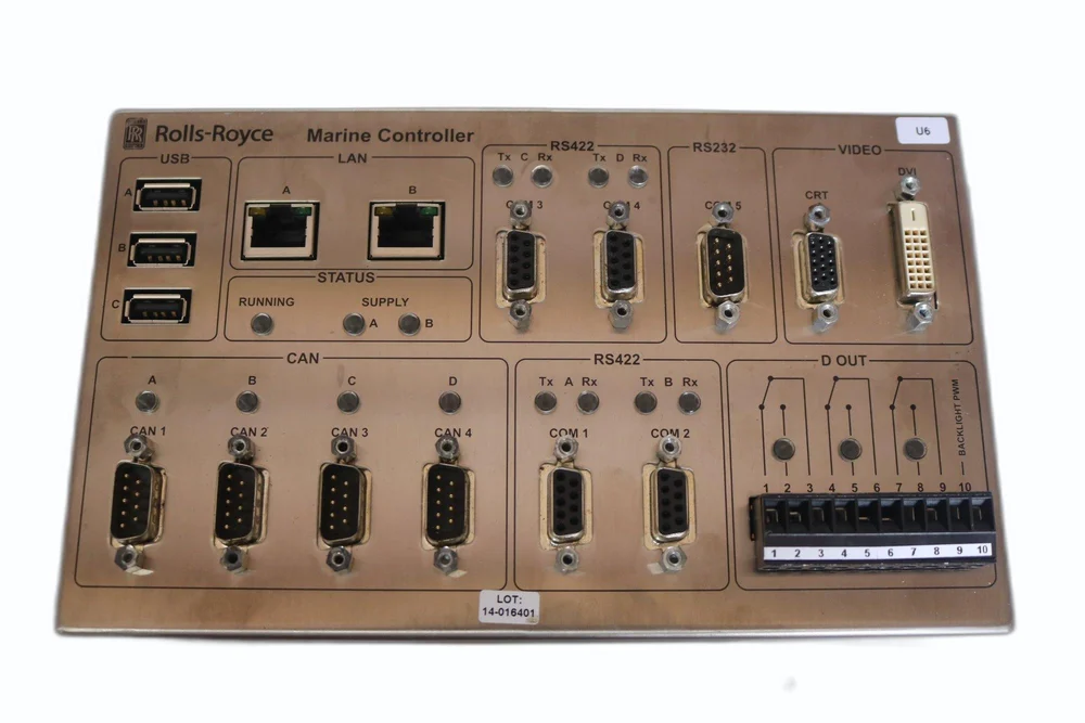
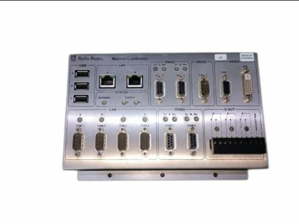
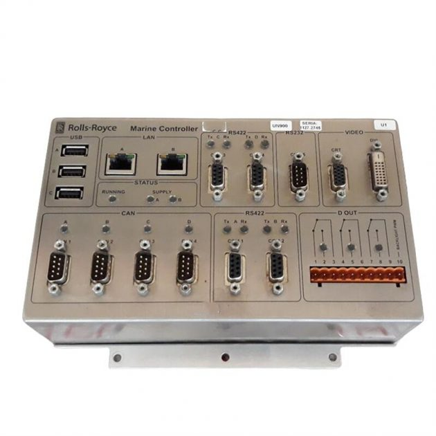
Strong compatibility: It should be equipped with rich and diversified standardised hardware interfaces, such as common RS-232, RS-485 serial communication interface, CAN bus interface, and various analogue and digital input/output interfaces, etc., so as to facilitate the physical connection with the engine control system, generator control system, navigation system, steering control system and other equipments, and to realise data sharing and cooperative work among equipments. Collaborative work. At the software level, it supports MODBUS, PROFIBUS and other general industrial communication protocols, as well as specific communication protocols for the shipbuilding industry, so that it can be seamlessly connected with different brands and models of ship equipment without complex interface conversion or customised development, which greatly improves the efficiency and flexibility of ship system integration.
Other models H1111.0102 model of the same series, the working voltage is 220 (presumed to be a common working voltage range), the output frequency is WEV39874 (although the meaning is not clear, but reflects that it has the ability to output at a specific frequency).H1111.0204 model, Part No. 75670, the working frequency is H6036/1.0GHz, serial.no. 1111.7261, the delivery software is 1111.7261, the output frequency is H6036/1.0GHz. 1111.7261, delivered software including bios k6036001.008, pic code rev 2.2. The characteristics of these models in terms of frequency, software version, etc. reflect that Rolls-Royce Marine Controller series are constantly optimised and upgraded, and each model meets diversified ship control needs through different parameter settings on the basis of maintaining the common advantages of the brand, and H1111.0104 will also follow this product development idea to innovate and improve in performance and functions.
Specification Parameters Model and version The model number of this marine controller is H1111.0203, which represents a unique design idea and function setting in the Rolls-Royce marine controller product matrix. It is equipped with PIC code version 2.2, which has been continuously optimised and has more precise control logic, which can greatly improve system compatibility and provide solid guarantee for the coordinated operation of marine equipment.
Communication Frequency Although the current public information has not yet disclosed the specific communication frequency of H1111.0203 marine controller, it can be seen by referring to the Rolls-Royce products of the same type that its communication frequency must have been professionally and finely tuned. In this way, it can operate stably in the complex and changeable electromagnetic environment of the ship and smoothly realise high-speed and reliable data transmission and command interaction with all equipments of the ship, which can strongly guarantee the efficient operation of the ship control system.
Other Parameters Due to the limitations of the available information, the specific parameters of the controller in terms of size, weight, working voltage, etc. are not clear for the time being. However, according to Rolls-Royce’s consistent design concept, its structural design will definitely take into account the compact layout and durability. Not only can it be cleverly adapted to the limited installation space of the ship, but also can maintain stable and reliable performance under the harsh marine environment. Skills
High reliability and stability Rugged protection design H1111.0203 marine controller shell selection of high-strength, corrosion-resistant special alloy materials, the face of seawater erosion, salt spray corrosion and humid air intrusion, can easily cope with. Even in the harsh marine environment for a long time, it can effectively prevent the shell from rusting and deformation, and build a reliable physical protection barrier for the internal precision electronic components. At the same time, the internal circuitry is reinforced with advanced potting technology, which significantly enhances vibration and shock resistance, significantly reducing the risk of failure caused by ship bumps and shaking, and ensuring that the controller’s performance is always stable during long-term operation.
Excellent anti-interference ability There are many electronic equipments on the ship, and the electromagnetic environment is complicated. This controller is equipped with multiple electromagnetic shielding measures, from the careful layout of the circuit board to the overall structure of the shield cleverly designed to isolate the external electromagnetic interference on the internal circuit. At the software level, it adopts advanced anti-interference filtering algorithms, monitors and processes input and output signals in real time, and automatically screens and rejects interfering signals to ensure that the instructions received and sent by the controller are accurate, thus realising the stable control of marine equipment.
Precise Intelligent Control Advanced control algorithm The controller has built-in advanced control algorithms based on Rolls-Royce’s many years of technological accumulation and R&D crystallisation. It can quickly and accurately calculate the optimal control parameters of the ship’s equipment according to the actual running state of the ship, the feedback data from real-time sensors and the commands given by the operator. Whether it is to adjust the engine speed according to different sailing speeds and load requirements, or to accurately control the rudder angle to achieve the ship’s steering, H1111.0203 Marine Controller is able to perform its tasks with high precision, ensuring that the ship can maintain optimal operating conditions under all kinds of working conditions.
Intelligent sensor co-operation The controller cooperates with various high-precision sensors such as speed sensors, pressure sensors and position sensors on the ship. By collecting and analysing the sensor data in real time, it can fully grasp the operating conditions of the ship’s equipment, make intelligent decisions and control accurately according to the preset procedures and algorithms. For example, it can automatically and flexibly adjust the engine power and rudder operation when it detects changes in the sea conditions to ensure the safety and stability of the ship’s navigation.
High compatibility Rich hardware interface H1111.0203 marine controller is equipped with a rich variety of standardised hardware interfaces, common RS-232, RS-485 serial communication interface, CAN bus interface, as well as all kinds of analog and digital input and output interfaces. With the help of these interfaces, it can be conveniently connected to the engine control system, generator control system, navigation system, steering control system and other equipment on the ship to achieve physical connection, and smoothly realise data sharing and collaborative operation among different equipment.
Wide range of software protocol support At the software level, the controller supports MODBUS, PROFIBUS and other general industrial communication protocols, as well as specific communication protocols for the marine industry. This enables it to work seamlessly with different brands and models of marine equipment without the need for cumbersome interface conversion or custom development, which greatly improves the efficiency and flexibility of marine system integration and effectively reduces system construction costs. Convenient Maintenance
Modular design The controller adopts modular design concept, divided into power supply module, communication module, control computing module, input and output module and other functionally independent modules. Once a module fails, maintenance personnel can quickly locate the problem and directly replace the corresponding module, without the need for large-scale disassembly and testing of the entire controller, significantly shortening the maintenance time and reducing the difficulty and cost of maintenance.
Intelligent Fault Diagnosis It has a built-in intelligent fault diagnosis system, which can monitor and analyse its own operation status in real time. Once a fault is detected, the system instantly generates a detailed fault report covering the type of fault, the location of the fault, the possible causes and other key information. Maintenance personnel can quickly read the fault report through the controller’s own display, or connect to external computers and other equipment, and carry out targeted maintenance work, significantly improving the efficiency of fault detection and repair.
Brand Background Rolls-Royce, as a long-established and influential British high-end manufacturing brand, has long been famous for its luxury cars and state-of-the-art aero-engines. In the field of marine equipment, Rolls-Royce also shows extraordinary technical strength and innovation. With its profound accumulation in many fields such as mechanical engineering, electronic technology and material science, as well as its extreme pursuit of quality and performance, the marine controllers developed by Rolls-Royce occupy an important position in the global marine market. Its products not only represent the leading level of the industry, but also provide a solid guarantee for the safe and stable operation of all kinds of vessels with their reliable, efficient and intelligent features, and are trusted by shipping enterprises, ship manufacturers and maritime agencies.
Specification Model identification: Model number H1111.0102, this specific model has a clear positioning in the Rolls-Royce marine controller product sequence, representing a unique functional configuration and technical standards, and is an important identification to distinguish it from other models. Communication Frequency: In terms of data transmission and command interaction, H1111.0102 marine controller is equipped with a communication frequency setting that is suitable for the complex electronic environment of ships, which can ensure a stable connection with various types of marine equipment, efficient transmission of control commands and operational data, and guarantee the smooth operation of the ship control system. However, due to the limited public information, the specific communication frequency parameters are not yet clear, and will be added in time if more information becomes available. Code Version: Adopting advanced control procedures, the current code version helps to achieve precise and intelligent control of ship equipment. Its continuously optimised algorithms and functions can adapt to the ever-changing operational requirements of the ship and enhance the stability and reliability of equipment control. Although it is not possible to obtain the exact code version number for the time being, but referring to other Rolls-Royce marine controllers, this version has outstanding performance in terms of compatibility and performance optimisation.
Skill features High reliability and stability Rugged and durable structural design: The shell of H1111.0102 marine controller adopts high-strength, corrosion-resistant special alloy materials, which can effectively resist the effects of seawater erosion, salt spray corrosion and humid environments, and still maintains the structural integrity under the harsh marine conditions, providing reliable physical protection for the internal precision electronic components. At the same time, its internal circuit layout is carefully designed, using high-quality electronic components, and through advanced welding technology and potting technology, to enhance the equipment’s vibration and shock resistance, reduce the risk of failure due to the ship’s bumps and shaking, to ensure that the controller always maintains a stable performance in the long-term operation of the process. Excellent anti-interference ability: there are many electronic devices on the ship, the electromagnetic environment is complex, H1111.0102 marine controller is equipped with multiple electromagnetic shielding measures, from the optimisation of the layout of the circuit board to the overall structure of the shield design, can effectively block the external electromagnetic interference on the internal circuit. In addition, at the software level, advanced anti-interference filtering algorithms are adopted to monitor and process the input and output signals in real time, automatically identify and reject the interference signals to ensure that the instructions received and sent by the controller are accurate, thus realising the stable control of marine equipment.
Precise Intelligent Control Advanced control algorithm: Built-in advanced control algorithm based on Rolls-Royce’s many years of technological research and development achievements can quickly and accurately calculate the optimal control parameters for each piece of equipment of the ship according to the actual running state of the ship, real-time sensor data and the operator’s instructions. Whether it is adjusting the engine speed to adapt to different sailing speeds and load requirements, or controlling the helm angle to achieve precise steering, H1111.0102 marine controller can complete the task with high precision, ensuring that the ship can maintain the best operating condition under various working conditions. Intelligent Sensor Fusion: Deep fusion with all kinds of high-precision sensors on the ship, such as speed sensors, pressure sensors, position sensors and so on. By collecting and analysing sensor data in real time, the controller is able to fully grasp the operating conditions of the ship’s equipment and make intelligent decisions and control based on preset procedures and algorithms. For example, when detecting changes in sea conditions, the controller can automatically adjust the engine power and rudder operation to ensure the safety and stability of ship navigation.
High compatibility Rich hardware interfaces: H1111.0102 marine controller is equipped with diversified and standardised hardware interfaces, including common RS-232, RS-485 serial communication interfaces, CAN bus interfaces, as well as various types of analog and digital input and output interfaces. These interfaces can be conveniently connected to the engine control system, generator control system, navigation system, steering control system and other equipment on the ship to achieve data sharing and cooperative work between different devices. Wide range of software protocol support: At the software level, it supports a variety of general industrial communication protocols such as MODBUS, PROFIBUS, etc., as well as communication protocols specific to the marine industry. This enables H1111.0102 marine controller to seamlessly interface with different brands and models of marine equipment without complex interface conversion or custom development, greatly improving the efficiency and flexibility of marine system integration and reducing system construction costs.
Convenient maintenance Modular design: Adopting the modular design concept, the controller is divided into several functionally independent modules, such as power supply module, communication module, control computing module, input and output module, etc. When a module fails, the maintenance of the controller is not necessary. When a module fails, maintenance personnel can quickly locate and directly replace the corresponding module, without the need for large-scale dismantling and testing of the entire controller, greatly reducing the maintenance time, reducing the difficulty and cost of maintenance. Intelligent fault diagnosis: Built-in perfect intelligent fault diagnosis system, which can monitor and analyse its own operation status in real time. Once a fault is detected, the system will immediately generate a detailed fault report, including information on the type of fault, the location where the fault occurred, and the possible causes. Maintenance personnel can quickly read the fault report through the controller’s own display or connect to external devices (such as computers), so as to carry out targeted maintenance and improve the efficiency of troubleshooting and repair.
Specification Types: Introduces the 5 Rolls-Royce specification types, clarifying their role and scope of application. RRDS (Rolls-Royce Design Standards): internal document providing information on design guidance, material selection, etc., not used for component definition. RRES (Rolls-Royce Engineering Standards): an external generic document that is followed by suppliers without separate approval, but requires approval for specialised processes and is used for component definition. RRMS (Rolls-Royce Material Specification): External document specifying requirements for material composition, manufacturing methods, properties, etc., used for component definition. RRP (Rolls-Royce Process Specification): an external document describing the requirements for the operation of the process, listing the key control variables, etc., mostly related to special processes, used for the definition of the component or specified by other specifications. RRQ (Rolls-Royce Quality Standard): an external document covering component or material quality standards, used for component definition and may relate to NDT process specifications.
Specification parameters Model and Part Number: Model number H1127 – 0101, Rolls-Royce part number 000068308 This unique combination acts as an exclusive ‘ID card’ for the product, facilitating accurate identification and management during production, sales and after-sales, and highlighting its specific positioning and design guidelines within the Rolls-Royce Marine Controller product line. Frequency: The working frequency is set to H6045/433 MHZ, which has been carefully adjusted to effectively avoid signal interference with other electronic equipment on the ship, ensure stable and high-speed data transmission and command interaction between the controller and various controlled equipment, and maintain smooth operation of the ship control system.
PIC code version: Currently at version 2.2, PIC (Peripheral Interface Controller) code is a key part of the controller’s core operating procedures, and version update means continuous optimisation of functions. 2.2 version further improves the compatibility with all kinds of equipment on board, the precision of control algorithms and the stability of the system operation on the basis of the previous version, which brings a better experience for users. Although the weight information of this controller is not yet available, we can refer to other marine controllers of the same brand. Reasonable weight design usually takes into account the ease of installation of the equipment and the stability of the vibration environment of the ship, which will not cause too much burden to the ship’s load and space layout, and at the same time, it can resist the vibration of the ship’s hull by its own weight and solid mounting structure, to ensure that the equipment works properly.
Skill features High reliability Material selection: the probability of using high-strength, corrosion-resistant special alloys to create the shell, can effectively resist seawater erosion, salt spray corrosion and humid air, long-term in the harsh marine environment, but also to prevent the shell from rusting, deformation, for the internal precision electronic components to provide reliable physical protection. Manufacturing process: Referring to the products of the same brand, the internal electronic components may be strictly screened and assembled through high-precision chip and welding process, with solid solder joints and stable electrical connections. Advanced potting technology is used in production to encapsulate key circuit modules in special insulating and moisture-proof materials to enhance vibration and shock resistance as well as waterproof and dustproof capabilities, significantly reducing the incidence of failures caused by environmental factors. Anti-interference design: It is very likely to be equipped with multiple electromagnetic shielding measures, from the circuit board layout to the overall structure of the shield set up, all-round blocking the external electromagnetic interference on the internal circuitry. Software algorithm level, the use of advanced anti-interference filtering technology, real-time monitoring and processing of input and output signals, automatic identification and elimination of interfering signals, to ensure that the controller receives and sends commands accurately, to maintain stable operation of the ship control system.
Precise control Control algorithm: Built-in advanced and complex control algorithm can accurately calculate the control parameters of each equipment of the ship in real time according to the running state of the ship, the feedback data from the sensors and the instructions of the operator. For example, when adjusting the engine speed, it can integrate the ship’s load, sailing speed requirements, sea conditions and other factors to accurately control the amount of fuel injection or motor output power, so as to realise precise adjustment of the engine speed within a very small error range. Sensor co-operation: It works closely with all kinds of high-precision sensors such as speed sensors, pressure sensors, position sensors, etc. on the ship. Rapid and accurate collection of sensor data, timely grasp of the actual operating conditions of the ship’s equipment, based on which control decisions are quickly made to achieve fine control of the ship’s equipment, to meet the stringent requirements for the ship’s control accuracy under different navigational conditions, such as entering and exiting ports, ocean voyages, and coping with adverse sea conditions.
Strong compatibility Hardware interfaces: Referring to other Rolls-Royce marine controllers, H1127-0101 is likely to have rich and diversified standardised hardware interfaces, such as common RS-232 and RS-485 serial communication interfaces, CAN bus interfaces, and various types of analog and digital input and output interfaces. It is convenient to be physically connected with the ship’s engine control system, generator control system, navigation system, steering control system and other devices to achieve data sharing and collaborative work between the devices. Software protocol: Support MODBUS protocol, PROFIBUS protocol and other general industrial communication protocols, as well as specific communication protocols for the marine industry. At the software level, it can be seamlessly connected with different brands and models of marine equipment without complex interface conversion or custom development, which improves the efficiency and flexibility of marine system integration and reduces the system construction cost.
Easy Maintenance Modular structure: the overall design or modular concept, divided into power modules, communication modules, control computing modules, input and output modules and other functional independent modules. When the module failure, maintenance personnel can quickly locate and directly replace, without large-scale dismantling and testing of the entire controller, greatly shortening the maintenance time and reducing the difficulty of maintenance. Fault diagnosis: It is very likely to be built-in perfect fault diagnosis system, real-time monitoring and analysis of its own operating status. Once a fault is detected, a fault report containing detailed information on the type, location, and possible causes of the fault will be generated immediately. Maintenance personnel can read the report through the controller’s own display or connected to an external computer, targeted maintenance, reducing troubleshooting time, improve maintenance efficiency. Convenient maintenance design: The enclosure is designed with full consideration of maintenance convenience, with easy-to-open and close access doors or covers, neat and orderly internal wiring, clear labelling, and key components are equipped with easy-to-plug connection interfaces, making it convenient for maintenance personnel to carry out daily inspections, cleaning, and replacement of components and other maintenance work.
Brand Background Rolls-Royce, as a British brand with deep heritage and excellent reputation, has left its mark in several high-end manufacturing fields. In the automotive field, its luxury cars have become synonymous with the world’s top luxury cars for their extreme craftsmanship, luxurious interiors and outstanding performance. In aerospace, Rolls-Royce’s engine technology is a world leader, providing powerful and reliable power for many advanced aircraft models. In the field of marine equipment, Rolls-Royce has also demonstrated its extraordinary strength. Since its entry into this field, it has rapidly become a leading supplier of key equipment such as marine controllers by virtue of its accumulated technological advantages in machinery manufacturing, electronic control and material science. Over the years, Rolls-Royce has always been persistently pursuing quality, strictly following the international high standards in product development and production, and each marine controller has gone through countless harsh tests and optimisation to ensure its stable operation in the complex, changeable and harsh marine environment, and provide a solid guarantee for the safe navigation and efficient operation of the vessels, which is why its products are trusted and favoured by the global shipping enterprises, yacht manufacturers and maritime agencies. and maritime organisations around the world.
Specification Model and part number: The model number of this marine controller is H1111.0103, and the Rolls-Royce exclusive part number is 75669. This specific combination of model number and part number is like a unique ‘ID card’ of the product, which not only facilitates accurate identification and management in production, sales and after-sales, but also reflects its specific positioning and design standards in Rolls-Royce marine controller product line.
Frequency: The working frequency is h6029/300MHz, which is carefully adjusted to avoid signal interference with other electronic equipment on the ship, ensuring stable and high-speed data transmission and command interaction between the controller and various controlled devices, and guaranteeing the smooth operation of the ship control system. Weight: about 2.040kg. Reasonable weight design takes into account the convenience of equipment installation and stability in the vibration environment of the ship. It will not bring a big burden to the ship’s load and space layout due to excessive weight, but can effectively resist the vibration and shaking of the ship’s hull when the ship is sailing with its own weight and stable mounting structure, so as to maintain the normal working condition of the equipment.
PIC code version: Currently it is version 2.2. PIC (Peripheral Interface Controller) code is a key part of the core running program of the controller, and its version is constantly updated, which means that its functions are optimised and perfected. 2.2 version, on the basis of the previous version, further improves the compatibility with all kinds of marine equipment, the accuracy of the control algorithm and the function of the control algorithm. Version 2.2, on the basis of the previous version, further improves the compatibility with all kinds of marine equipment, the accuracy of control algorithms and the stability of the system operation, which brings users a better experience.
Characteristics High reliability Material selection: the shell is made of high-strength, corrosion-resistant special alloy material, which can effectively resist the erosion of seawater, salt spray corrosion and the influence of humid air, even if it is in a harsh marine environment for a long period of time, it can also prevent the shell from rusting and deformation, so as to provide reliable physical protection for the internal precision electronic components. Manufacturing process: the internal electronic components are assembled through strict screening and high-precision SMD and welding processes, with solid solder joints and stable electrical connections. At the same time, in the production process, the use of advanced potting technology, the key circuit modules will be potting in a special insulation, moisture-proof materials to further enhance its resistance to vibration, shock, and waterproof, dust-proof ability, greatly reducing the probability of failure due to environmental factors.
Anti-interference design: Equipped with multiple electromagnetic shielding measures, from the layout design of the circuit board to the overall structure of the shielding setup, effectively blocking the influence of external electromagnetic interference on the internal circuitry of the controller. In addition, at the level of software algorithm, it adopts advanced anti-interference filtering technology, which can monitor and process the input and output signals in real time, and automatically identify and reject the interference signals, so as to ensure that the commands received and sent by the controller are accurate, and to guarantee the continuous and stable operation of the control system of the ship.
Precise control Control Algorithm: Built-in advanced and complex control algorithm can accurately calculate the control parameters for each equipment of the ship in real time according to the ship’s operation status, sensor feedback data and operator’s instruction. For example, when adjusting the engine speed, it can accurately control the fuel injection volume or motor output power according to the ship’s load, sailing speed requirements, sea conditions and other factors, so as to realise the precise adjustment of the engine speed and control the error within a very small range. Sensor co-operation: It works closely with all kinds of high-precision sensors on the ship, such as speed sensors, pressure sensors, position sensors and so on. Through fast and accurate collection of sensor data, the controller can grasp the actual operating condition of the ship’s equipment in time and make corresponding control decisions accordingly, realising fine control of the ship’s equipment and meeting the stringent requirements for ship control accuracy under different navigational conditions (e.g. entering and exiting ports, ocean voyages, coping with adverse sea conditions, etc.). S
trong compatibility Hardware interfaces: It has rich and diversified standardised hardware interfaces, such as common RS-232 and RS-485 serial communication interfaces, CAN bus interfaces, and various analogue and digital input and output interfaces, etc. These interfaces can be easily and quickly connected with the ship’s equipment. These interfaces can be easily and quickly connected to the ship’s engine control system, generator control system, navigation system, steering control system and other equipment for physical connection, to achieve data sharing and cooperative work between different devices. Software protocol: It supports a variety of common industrial communication protocols, such as MODBUS protocol, PROFIBUS protocol, etc., as well as some specific communication protocols for the marine industry. This makes the controller in the software level with different brands and models of marine equipment to achieve seamless docking, without the need for complex interface conversion or custom development, greatly improving the efficiency and flexibility of the marine system integration, reducing the system construction costs.
Easy maintenance Modular structure: The overall design adopts the modular concept, dividing the controller into several functionally independent modules, such as power supply module, communication module, control computing module, input and output module, etc. When a module fails, it is easy to maintain. When a module fails, maintenance personnel can quickly locate and directly replace the corresponding module, without the need for large-scale dismantling and testing of the entire controller, greatly shortening the maintenance time and reducing the difficulty of maintenance. Fault diagnosis: The built-in perfect fault diagnosis system can monitor and analyse its own operation status in real time. Once a fault is detected, the system immediately generates a detailed fault report, including the type of fault, the location of the fault, the possible causes and other information.
Maintenance personnel can read the fault report through the controller’s own display or connected to external devices (such as computers), so as to carry out targeted maintenance, reducing fault detection time and improving maintenance efficiency. Convenient maintenance design: the controller’s shell design gives full consideration to the convenience of maintenance, with easy-to-open and close access doors or covers, neat and orderly internal wiring and clear labelling, and key components are equipped with easy-to-plug connection interfaces, which is convenient for maintenance personnel to carry out daily inspection, cleaning and component replacement and other maintenance work.
Scenario Application Merchant Marine Cargo ships: For all kinds of cargo ships with huge cargo carrying capacity, it is necessary to ensure that the power system of the ship always operates stably and efficiently during the long-distance transport. Rolls-Royce H1111.0103 marine controller can accurately control the output power of the engine, adjust the engine speed and fuel injection volume in real time according to the cargo ship’s load, the sea conditions of the sailing routes and the optimization demand of fuel consumption, so as to ensure the ship’s sailing speed while minimizing fuel consumption and improving the economy of transportation. In addition, through the co-operation with the navigation system, the controller can also accurately control the steering of the rudder according to the route information, to ensure that the cargo ship navigates safely and accurately along the predetermined route, and to avoid navigational delays or safety risks due to deviation of the heading.
Oil tankers: Oil tankers transport flammable and explosive oil and other dangerous chemicals, which requires high safety and stability of the ship. The application of the controller on the tanker can, on the one hand, reliably control the power system and auxiliary equipment of the tanker, ensure the smooth operation of the ship during navigation, and reduce the safety risks caused by equipment failure. On the other hand, by connecting with the liquid level monitoring system and oil temperature control system on the tanker, the controller can grasp the status of the cargo in the tank in real time and automatically control the related equipments according to the preset parameters, such as oil pumps, heating devices, etc., so as to guarantee the safety and quality of the cargo transport process.
Container ships: Container ships usually need to enter and exit ports frequently, which requires more demanding requirements on the manoeuvrability of the ships. Rolls-Royce marine controller, with its precise control ability, can quickly and accurately control the start and stop of the engine, the change of rotational speed and the steering angle of the rudder when the ship enters and leaves the port, so that the ship can flexibly cope with the complex environment of the port waters, such as narrow fairways, dense ship traffic, and so on. Meanwhile, during ocean voyage, the controller can optimise the power distribution of the ship according to the cargo layout and sailing status of the container ship to ensure the stability and safety of the ship during high-speed voyage.
Yacht field Luxury yachts: luxury yacht users are often in pursuit of the ultimate sailing experience and high-end control performance, H1111.0103 marine controller can provide luxury yachts with precise and sensitive control feeling. By integrating with the advanced cockpit control system on the yacht, the driver can easily control all the equipments of the vessel through the operation console, such as the acceleration and deceleration of the engine, the steering of the yacht, the mooring and other operations can be achieved with precise response, which can bring the driver a smooth and enjoyable experience like driving a top-class sports car. In addition, the controller can also be linked with the yacht’s entertainment system, air conditioning system and other auxiliary equipment, according to the driver’s needs to automatically adjust the operating state of the relevant equipment, creating a comfortable and pleasant sailing environment.
Warship field Combat ships: When warships carry out combat missions, they are faced with the complex, changing and dangerous environment of the sea battlefield, which has extremely high requirements on the mobility, reliability and response speed of the ships. Rolls-Royce marine controllers can work stably under harsh electromagnetic interference, wave impact and other environments, and provide reliable control support for the power system, weapon system and all kinds of on-board equipment of warships. For example, when the ship carries out high-speed evasive manoeuvres, the controller can quickly adjust the engine power and rudder steering, so that the ship can quickly and flexibly change the heading and speed to avoid enemy attacks. At the same time, through the close connection with the ship’s combat command system, the controller can accurately control the start of the weapon system, targeting and launching operations according to the combat instructions, providing a strong guarantee for the combat effectiveness of the warship.
Patrol ships: Patrol ships need to cruise on the sea for a long time when carrying out daily patrol and alert tasks, which requires high stability and durability of the equipment. The controller can ensure the continuous and stable operation of the power system of the patrol ship, reduce the failure rate of the equipment, and reduce the interruption of the patrol mission caused by equipment maintenance. Moreover, by working with the ship’s reconnaissance equipment and communication equipment, the controller can flexibly adjust the ship’s sailing speed and position according to the needs of the reconnaissance mission, guaranteeing the optimal working condition of the reconnaissance equipment, and at the same time, ensuring the stable connection of the communication equipment, realising the real-time information interaction with the command centre.
Installation requirements: For use in industrial environments of pollution class 2, overvoltage category II, at an altitude of up to 2000 metres above sea level, as Group 1, Class A industrial equipment. Installation in a flame-retardant, tool-accessible enclosure is required to meet EMC and safety requirements. Use zinc-plated yellow chrome steel DIN rails for grounding and avoid using other rail materials that may cause poor grounding.
Approved for use in hazardous areas North America: Some modules (1794-OB8, 1794-OB8EP, 1794-OB16, 1794-OB16P) are approved for use in hazardous areas in North America. The products are labelled with a temperature code, and when combining devices, attention should be paid to the overall temperature code and local regulatory review. When operating in a hazardous area, it is strictly prohibited to disconnect or connect the device with electricity, and operations such as battery replacement should be performed in a non-hazardous area. Europe: Some modules (1794-OB8, 1794-OB8EP, 1794-OB16, 1794-OB16P) are certified for use in potentially explosive atmospheres by Zone 2 Europe. When in use the equipment has to fulfil specific conditions, such as protection against UV rays, avoidance of voltage overruns, etc.
Module Installation Preparation for Installation: The module should be mounted on a 1794 series terminal block, ensuring that no debris falls into the module prior to installation and that plugging or unplugging the module while it is energised may be hazardous. Installation Procedure: Turn the key switch to position 2, make sure the Flexbus connector is fully extended, insert the module and align it with the notch for a secure installation. Wiring Methods: Wiring methods vary between module models (1794-OB8, 1794-OB8EP, 1794-OB16, 1794-OB16P, 1794-OB32P). Output, power, and common wires need to be connected according to specific rules, and the power supply can be daisy-chained, and the total current must not exceed 10A.
Module Configuration 1794 – OB8EP Module: Configured by setting bits in the configuration word, fault bits can be programmed to detect faults, and faults can be reset by pushbuttons, programming, or cycling the backplane power. Other modules (1794-OB8, 1794-OB16, 1794-OB16P, 1794-OB32P): Configuration by setting the bits in the configuration word (word 3).
Note Zone Classification and Equipment Suitability: 1794-OB8 is suitable for use in North American Class I Division 2 Groups A, B, C, and D hazardous areas and European Zone 2 hazardous areas, but cannot be used in other hazardous area classifications. Hazardous area temperature codes are marked on the product nameplate. When using the product in a system combination, the most unfavourable temperature code (the lowest ‘T’ number) must be used to determine the overall system temperature code, and the combination of equipment must be reviewed by the local regulatory agency.
ELECTRICAL SAFETY OPERATIONS: Disconnecting equipment or connections while energised is strictly prohibited, and before operating in a hazardous area, you must either disconnect the power supply or ensure that the area is free of hazards. Plugging and unplugging modules under electrical power can cause arcing, which may result in an explosion, as well as wear and tear of the module and connector contacts, which can interfere with the normal operation of the equipment. When used in hazardous areas, prevent the rated voltage from exceeding the specified value due to transient disturbances, e.g. in European Zone 2 environments, take measures to ensure that transient disturbances do not cause the voltage to exceed 40% of the rated value.
Installation and earthing of the device: The device must be installed in a compliant enclosure with a minimum IP54 protection rating (required for European Zone 2 environments), with the interior accessible only by means of a tool, and with suitable flame retardancy to prevent the spread of flame. Use zinc-plated yellow chrome steel DIN rails for earthing, avoiding corrosive, oxidising or poorly conductive rail materials such as aluminium or plastic to prevent poor earthing. Securely fasten DIN rails to the mounting surface at intervals of approximately 200mm (7.8in.) and use end anchors where appropriate. Component and connection management: Avoid changing components as this may affect the suitability of the equipment for use in hazardous areas. Ensure that all external connections are securely fastened by screws, slide latches, threaded connectors, etc.
Troubleshooting and maintenance: The 1794 – OB8 module outputs are not fused and it is recommended that they are protected externally by a SAN – O MQ4 – 800mA fuse. In the event of a module fault, for the 1794-OB8EP module, the fault can be reset by pressing the fault reset button on the front of the module, toggling the output reset bit (Write 1, Bit 08), or cycling the backplane power.
IMPORTANT INFORMATION AND SAFETY NOTE: Solid-state equipment has different characteristics than electromechanical equipment and should be used in a manner that ensures application compliance. Rockwell Automation is not responsible for consequential damages arising from the use of the equipment, and the contents of this manual may not be reproduced without permission. The manual contains a variety of safety tips, such as operating in hazardous environments, risk of electric shock, and more.
System Design and Hardware Installation Design Steps: Designing a FlexLogix system involves determining the network configuration and component locations, and selecting the appropriate I/O devices, communication cards, controllers, power supplies, and software. Hardware Installation: Installation steps include mounting DIN rails, power supplies, batteries, communication cards, and connecting serial ports. The installation process requires attention to grounding, use of appropriate cables, and adherence to specifications.
Network Communication Supported Network Types: EtherNet/IP, ControlNet, DeviceNet, serial, DH-485 and third party networks are supported. Different networks have different communication methods, required software and hardware, and have different numbers of connections and configuration methods. Data interaction: The controller can produce (broadcast) and consume (receive) data, as well as send and receive messages over the network. Connections need to be planned appropriately to optimise communication performance.
I/O Configuration and Management Module Selection and Placement: Select the 1794 FLEX I/O modules according to your needs, determine their location in the local or distributed network, and select appropriate power supplies. Configuration and Monitoring: To configure an I/O module, set parameters such as Request Packet Interval (RPI), Change of State (COS), communication format, and electronic keying. The I/O module status can be monitored through the programming software and the module can be reconfigured if necessary.
Application Development Task and programme management: Scheduling and prioritising the execution of programmes using multiple tasks, with task types including continuous, cyclic and event tasks. Programs consist of tasks, program tags, master routines and other routines. Programming and Monitoring: Supports multiple programming languages such as Ladder Diagram (LD), Function Block Diagram (FBD), Sequential Function Chart (SFC) and Structured Text (ST). Controller status and connection status can be monitored via GSV and SSV commands. PhaseManager Configuration: PhaseManager provides a state model for the device, dividing the device’s operating cycle into different states and controlling state transitions through commands. It is used to meet specific system requirements, and different states and transitions have clear definitions and roles. Battery Maintenance: Introduces battery storage, life estimation and replacement methods. Environmental conditions should be taken into account when storing batteries, warnings are given when batteries are low, they need to be replaced at the specified time, and specific precautions should be followed when replacing them.
System Status Indication and Backup Status Indicators: Controller LEDs indicate the status of Run, Force, Battery, I/O, etc., reflecting system conditions through different colours and blinking patterns. DeviceNet Backup: FlexLogix’s backup system on DeviceNet utilises shared master technology for fast switchover in the event of a controller failure. Backup systems have specific hardware and software requirements and need to be configured and programmed accordingly.
Technical Specification Parameters Hardware Specifications Processor and Memory: Equipped with a high-performance processor (such as the 5434 processor) and 512KB of user memory for storing user programmes and data, it can meet the storage requirements of a variety of industrial automation applications. When dealing with small equipment control programmes, it can stably store programme codes and data during operation. Communication interface: 1 RS-232 serial port, supporting ASCII and DF1 protocols, can be used to connect barcode readers, operator terminals and SCADA systems. There are also two slots for installing 1788 communication cards, which can be used to communicate with Ethernet/IP, DeviceNet and ControlNet networks after installing the corresponding communication cards.
Electrical Specifications Power Requirements: External 24V DC supply from 19.2 – 31.2V DC (including 5% AC ripple). CSA-compliant Separated Extra-Low Voltage (SELV) power supplies such as 1794 – PS3 or 1794 – PS13 are available to meet specific standards. Current parameters: Input current max. 0.85A at 24V DC, max. 1.33A at 19.2V DC, Flexbus current output max. 653mA at 5.1V DC. Power and Thermal Dissipation: Power dissipation is 25.5W at 19.2V DC and 20.4W at 24V DC; thermal dissipation is 87BTU/hour at 19.2V. Isolation Voltage: Isolation voltage is 30V DC, after 850V DC test for 60s, it has good electrical isolation performance, which can effectively guarantee the safe operation of the system.
Environmental adaptability specifications Temperature range: Operating temperature 0 – 60°C (32 – 140°F), non-operating temperature – 40 – 85°C (-40 – 185°F), can adapt to a certain range of temperature changes, and can work stably in the industrial field environment. Humidity Requirements: Relative humidity requirements of 5 – 95% non-condensing, can operate normally in a wide range of humidity conditions, reducing failures caused by humidity problems. Vibration and shock tolerance: can withstand a certain degree of vibration and shock, running vibration is 5g (10 – 500Hz), running shock is 30g, non-running shock is 50g, to adapt to the complex physical environment of the industrial site.
Other Specifications Dimensions and Weight: Compact design for easy installation in small spaces, with specific dimensions of 7.87‘ (199.9mm) x 4.33’ (110mm) x 3.94’ (100mm) and weight of 2.2lbs (1.0kg) or 0.75kg. Mounting: DIN rail or panel mounting, flexible mounting, you can choose the appropriate mounting method according to the actual application scenarios. Certification: UL, CE and other industrial standards, in line with relevant safety and quality standards, can be used in different regions and industries.
IMPORTANT USER INFORMATION: Emphasises the differences between solid-state equipment and electromechanical equipment, use of this module is to ensure that the application complies with the requirements, Rockwell Automation is not responsible for consequential damages arising from the use of the equipment, and the manual examples are for reference only and may not be reproduced without permission. Also includes a variety of safety tips, such as operating in hazardous environments and protection against static electricity. Installation requirements: For use in pollution class 2, overvoltage category II, industrial environments up to 2000 metres above sea level, Group 1, Class A industrial equipment. Installation in a flame-retardant, tool-accessible enclosure to fulfil EMC and safety requirements. Use zinc-plated yellow chrome steel DIN rails for grounding and avoid using other rail materials that may cause poor grounding.
Approved for use in hazardous areas North America: This module is approved for use in hazardous areas in North America. The product is labelled with a temperature code and the overall temperature code and local regulatory review should be noted when combining devices. When operating in a hazardous area, electrical disconnections or connections are not permitted, and operations such as battery replacement must be performed in a non-hazardous area. Europe: European Zone 2 approved for use in potentially explosive atmospheres. The device must be used in an enclosure of at least IP54 protection, protected from direct sunlight, protected from voltage overruns, and must have an ATEX approved backplate.
Module Installation Preparation for Installation: The module must be used with either the 1794-TB3G or 1794-TB3GS terminal block. Ensure that no debris has fallen into the module prior to installation, and disable the keying function in the configuration file when replacing a Series A module with a Series B module. Installation Procedure: Rotate the key switch to position 3, ensure the Flexbus connector is fully extended, insert the module and align it with the notch for a secure installation. Once installed, remove the end cap plug and connect additional terminal blocks if required.
Wiring and Grounding Wiring: When connecting a two-wire transmitter device, the input, power, and common wires need to be connected according to specific rules, power supplies can be daisy-chained, and analogue and digital modules should be powered separately to minimise noise interference. Grounding: All I/O wiring must be shielded and the shield must be externally grounded to the module, e.g. to a busbar or shielded ground feedthrough.
Module Configuration: Set module parameters such as byte order, data format, digital filters, alarm limits, etc. through the configuration mapping table. The data format is various and can be selected according to requirements. Different settings correspond to different functions and value ranges. The configuration in Series A mode is different from that in Series B mode, so it is necessary to pay attention to the applicable scenarios.
HART input data: HART input data contains the main variables of the device and other information, if the HART communication of the channel is disabled, the input data of the channel may be zero, HART input data word contains the communication status, device status, variable acquisition and other information, and each status bit has a clear meaning.
Status Indicators: The module is equipped with 8 red fault indicators, 8 yellow channel indicators and 1 green power indicator. Different indicator statuses reflect different working statuses of the module, such as blinking red indicates channel fault, green light indicates normal power supply, blinking green indicates no Flexbus communication, and yellow light indicates normal HART communication.
Basic Parameters Number and type of inputs: 8 single-ended, non-isolated analogue input channels, suitable for analogue signal acquisition in various industrial scenarios. Recommended Terminal Block: Adapted to 1794-TB3G and 1794-TB3GS terminal blocks, ensuring stable connection between the module and external devices. Key switch position: fixed to 3, used to set the module’s working mode. Enclosure type rating: None (open), to be installed in an additional protective enclosure to meet the protection requirements of the specific application environment.
Electrical parameters Resolution and data format: resolution up to 16 bits, data format can be configured to support a variety of data representation to meet different measurement and control needs. Conversion correlation: using the successive approximation method for conversion, can accurately convert analogue signals to digital signals. Accuracy and anti-interference: Absolute accuracy of 0.1% full scale at 20°C (68°F), 0 – 55°C (32 – 131°F) accuracy drift of 0.05% full scale, with good stability. It has a certain ability to suppress interference signals of different frequencies, which can ensure the accuracy of the signal to a certain extent. Input Characteristics: Input terminals are specifically numbered for connection to external signals. When the 24V DC power supply is removed, the input resistance becomes 10 kΩ. Isolation and power supply: Isolation voltage is 50V (continuous), basic insulation type, tested at 850V DC for 1s to ensure electrical safety Flexbus current is 80 mA at 5V DC and 190 mA at 24V DC; power supply requirements are 24V DC (voltage range 19.2-31.2V DC with 5% AC ripple), powered by a 1794-PS13 power supply at 31.5V DC. The PS13 power supply has a maximum power consumption of 3.9W at 31.2V DC and a maximum thermal dissipation of 13.5BTU/hr.
Physical Parameters Dimensions and Weight: Measures approximately 46.0 x 94.0 x 75.0mm (1.8 x 3.7 x 2.95in.) when mounted and weighs approximately 200g (7.05oz) for ease of installation in equipment layouts. Indicator Lights: Equipped with 8 red fault indicator lights, 8 yellow channel indicator lights and 1 green power indicator light, which indicates the working condition of the module through different colours and statuses for easy monitoring. Wire-related: Wire size is determined by the installed terminal block, shielded wires are used for signal ports, and the wiring category is Class 2 for both signal and power ports, which can be used for planning wire routing.
Environmental parameters Temperature range: Operating temperature – 20 – 55°C (-4 – 131°F), storage temperature – 40 – 85°C (-40 – 185°F), can be adapted to a certain range of temperature changes . Humidity and others: Relative humidity requirements of 5 – 95% non-condensing; able to withstand a certain degree of vibration and shock, vibration conditions for the 2g @ 10 – 500Hz, operating shock and non-operating shock of 15g; in terms of electromagnetic compatibility, in line with the relevant standards, such as CISPR 11 in the Group 1, Class A standards (with a suitable enclosure), the Electrostatic Discharge (ESD), radiation radio frequency (RF), electrical rapidity of (It is immune to electrostatic discharge (ESD), radiated radio frequency (RF), electrical fast transient pulse bursts (EFT/B), surge transients and conducted RF.
IMPORTANT USER INFORMATION: Solid-state equipment has different characteristics than electromechanical equipment and should be used in accordance with applicable safety guidelines to ensure application compliance. Rockwell Automation is not responsible for consequential damages arising out of the use of the equipment. The manual examples are for reference only and may not be reproduced without permission. The manual includes a variety of safety tips, such as operating in hazardous environments, risk of electric shock and burns, and more. Installation requirements: For industrial environments in pollution class 2, overvoltage category II, up to 2000 metres above sea level, Group 1, Class A industrial equipment. Installation in a suitable enclosure which is flame retardant and accessible only by means of tools, with attention to electromagnetic compatibility. Use zinc-plated yellow chrome steel DIN rails for grounding, avoiding corrosive, oxidised or poorly conductive rail materials.
Hazardous area approvals North America: The module is approved for use in hazardous areas in North America. The product is labelled with a temperature code, and when combining devices, attention should be paid to the overall temperature code and the local regulatory review, and it is strictly prohibited to electrically disconnect the device or make connections when operating in hazardous areas. Europe: The module is approved for use in potentially explosive environments in Europe Zone 2, with additional requirements for use, such as UV protection, enclosure protection levels, and avoidance of voltage overruns.
Installation steps Installation to Terminal Block: Install the module in the 1794 – TB3 or 1794 – TB3S terminal block, before installation, turn the key switch to position 3, make sure the Flexbus connector is fully extended, when inserting the module, pay attention to align the grooves and install it securely to prevent debris from falling into the module, as plugging and unplugging with electricity may be dangerous. Wiring: Connect the input, signal return, power and common wires to daisy chain the power supply. Use shielded wires and connect them to functional ground, which varies for different types of transmitters. Grounding: All I/O wiring must be shielded and the shield must be grounded on the outside of the module.
Module Configuration: Set module parameters such as byte order, digital filter, fault mode, HART current ratio, etc. through the configuration mapping table, different settings correspond to different functions and value ranges. There are various choices of data format, such as milliamps, percentage of full scale, etc. Some formats only support HART communication. HART input data: HART input data contains the main variables and other information of the device, and HART communication can be disabled through configuration.HART input data word contains information of communication status, device status, variable acquisition, etc., and each status bit has a clear meaning. Status Indicator: OK The status indicator is bicolour (red/green). Flashing green indicates that the module configuration word is zero, the 24V DC user power supply is off, or the module is in configuration mode; red indicates that the module has not passed the initial hardware test, and the module needs to be re-powered when the red indicator appears.
Basic Parameters Number and type of inputs: 8 single-ended, isolated analogue input channels, which can effectively avoid inter-channel interference and is suitable for industrial scenarios requiring isolated inputs. Recommended Terminal Block: For 1794-TB3 and 1794-TB3S terminal blocks to ensure stability and compatibility of the module with external devices. Key switch position: 3, the module can be adapted to the corresponding operating mode by setting a specific key switch position. Enclosure type rating: None (open), which means that the module can be used in an additional protective enclosure to meet the protection requirements of the specific application. Electrical parameters Resolution and Data Format: Resolution is 16-bit unipolar or 15-bit plus sign bit bipolar, with a current resolution of 0.320 µA/cnt in unipolar and 0.640 µA/cnt in bipolar. The data format supports engineering units, percentage full scale, and RAW/proportional counting to meet different data processing and display requirements.
Conversion related: Sigma Delta conversion type is adopted, and the conversion rate varies according to different settings, such as 4.17Hz, 10.0Hz, 16.7Hz, 19.6Hz, 62Hz, 470Hz, etc., in order to adapt to different measurement frequency requirements. Input current can be configured as 4 – 20mA or 0 – 20mA, output 0mA when not configured. Accuracy and immunity: Absolute accuracy 0.1% full scale at 25°C, accuracy drift 0.4% full scale from 0 – 55°C. Under normal mode, it has high rejection ratio for current signals of different frequencies, and the common mode rejection ratio is more than 60dB at 50Hz and 60Hz, which has good anti-interference ability.
Input Characteristics: The input resistance is 249Ω ±1%, which can acquire the input signal stably. The maximum overload is 32mA continuous (one channel at a time) to ensure the safety of the module under certain overload conditions. Isolation and power supply: Isolation voltage is 120V (continuous), basic insulation type, tested by 1000V AC for 60s, including isolation between user power supply and system, channel and system, and channel and channel.Flexbus current is 80mA @ 5V DC, used to supply power to the Flexbus interface of the module; maximum power consumption is 4.8W at 31.2V DC, and maximum heat dissipation is 16.4BTU. Maximum power consumption is 4.8W at 31.2V DC and maximum thermal dissipation is 16.4BTU/hr; external power supply requirements are 24V DC (19.2-31.2V DC with 5% AC ripple) and supply current is 190mA at 24V DC.
Physical Parameters Dimensions: Measures approximately 94 x 94 x 66mm (3.7 x 3.7 x 2.6in.) when mounted for easy installation in a facility. Indicator Lights: Equipped with 1 red/green power/status indicator light, which reflects the working status of the module through different colours and blinking status, e.g. blinking green indicates that the module’s configuration word is zero, the power is off, or it is in the configuration mode, while red indicates that it has not passed the initial hardware test. Wire-related: Wire size is determined by the installed terminal block, shielded wires are required, wiring category is divided into signal port category 2, power port category 3, which can be used for planning wire routing, and the grounding conductor should be equal to or greater than the phase conductor.
Manual Overview and the FLEX I/O System Manual Content and Purpose: Designed to guide the user through the use of the FLEX I/O analogue modules, covering installation, programming, and troubleshooting, this manual is intended for users who are able to operate Allen-Bradley programmable controllers and understand block transfer programming. The manual describes the FLEX I/O system components and the types of analogue modules that work together through adapters, terminal blocks and I/O modules, which are available in a variety of types to suit different applications. The FLEX I/O system consists of adapters, terminal blocks and I/O modules. Adapters provide internal logic power for multiple I/O modules; terminal blocks are used for wiring two- or three-wire devices; and I/O modules contain bus interfaces and circuits to perform specific functions.
Analogue Module Installation Prepare for installation: Calculate the power requirements of each module and ensure that the total current does not exceed 10A, otherwise a separate power supply is required. Confirm that the product complies with the EU directive, pay attention to static electricity protection during installation, and avoid removing or replacing the terminal blocks under charged conditions. Installation steps: Installation includes mounting the terminal block (DIN rail or panel/wall mounting available), mounting the analogue module to the terminal block (note the key switch position and the Flexbus connector status), and connecting the wiring (wiring varies between modules and terminal blocks). Once the module is mounted, the green power indicator shows whether the module is powered on or not.
Module Programming: The module communicates with the processor via a bi-directional block transfer. Configuration Block Transfer Write (BTW) is used to set up the module functions and Block Transfer Read (BTR) is used to get the module information. The manual gives programming examples for the PLC-3, PLC-5 and PLC-2 processors, emphasising the need to pay attention to the order in which the modules are powered up, the creation of data files and the monitoring of status bits. The analogue data format is 12-bit resolution, left-justified to a 16-bit field, with the highest bit being a sign bit.
Module Configuration and Data Reading Configuration method: When using the Remote I/O Adapter, module functions such as input/output range selection, safety status value selection, etc. are configured via block transfer write commands. The input channels can be configured with various voltage or current ranges and the output modules can be set with safety status values. Data reading: Transfer module status and data to processor data table through block transfer read command. Read/write words and bit/word descriptions are different for different modules, which need to be operated according to specific modules.
DeviceNet Communication and Mapping Communication structure: The DeviceNet Manager software is used to configure the FLEX I/O DeviceNet adapter and related modules. In the polled I/O structure, output data is received in module order, and input data is received first in the adapter status word and then in module order. Data Mapping and Default Values: It introduces the data mapping methods of different analogue modules in DeviceNet, as well as the default values and real-time size settings of the modules. The default values are assigned by the adapter when the system is first powered up and there are no previous stored settings, and the I/O data size can be adjusted according to the requirements.