Call us 24/7uaedcs@163.com
Welcome to the official website of CNIACS Automation Technology Co., Ltd!
Call us 24/7uaedcs@163.com

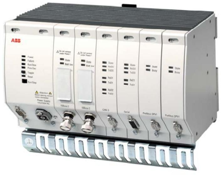
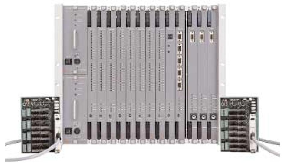
AC 800F Freelance 200 control system

Base unit technical data
Processor and memory: Intel 80960HT25/75 32-bit RISC Super Scalar microprocessor up to 150 MIPS. 4 MB static RAM, 4 MB Flash-EPROM, 16 K internal CPU cache RAM, 16 Kbit Serial EEPROM for PM 802F and 16 MB synchronous dynamic RAM, 8 MB Flash-EPROM, also with 16 K internal CPU cache RAM and 16 Kbit Serial EEPROM for PM 803F. The PM 803F has 16 MB of synchronous dynamic RAM, 8 MB of Flash-EPROM, 16 K of internal CPU cache RAM and 16 Kbit serial EEPROM.

Data Processing and I/O: 1000 instruction execution time, less than 1.0 ms for binary and 16-bit arithmetic, less than 2 ms for fixed-point arithmetic, and less than 1.5 ms for 32-bit arithmetic I/O scan cycle times are configurable, depending on fieldbus module capabilities.

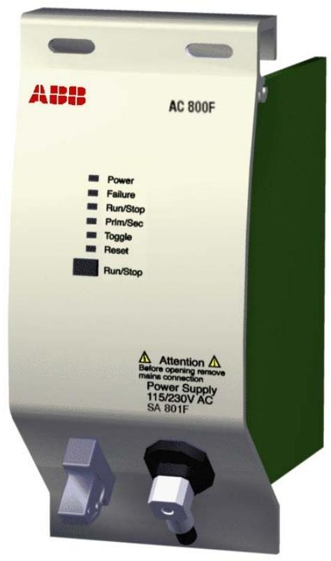
Power supply and physical specifications: The PM 802F base unit has a maximum power consumption of 6.3 W, the PM 803F 7.8 W. The power supply is available in 115 – 230 V AC (SA 801F/SA 811F) and 2 x 24 V DC (SD 802F/SD 812F). Weight max. 5 kg (fully assembled), dimensions W 239 mm, H 202 mm, D 164 mm.

Power supply module technical data

x 24 V DC (allowable range 19.2 – 32.5 V DC), SD 802F outputs 5 V DC / 5 A and 3.3 V DC / 5 A, SD 812F outputs 5 V DC / 5.5 A and 3.3 V DC / 6.5 A.
Other parameters: SA 801F rated input power 48 VA, SA 811F 63 VA; SD 802F rated input power 31 W, SD 812F 41 W. All of them are equipped with a power failure backup energy of more than 20 ms, short-circuit protection and current limiting function, SA 801F/SA 811F current limiting is about 6 A and 7.5 A respectively, SD 802F/SD 812F current limiting is about 6 A and 7.5 A respectively, SD 802F/SD 812F current limiting is about 5 V DC / 5 A and 3.3 V DC / 5 A respectively. The SA 801F/SA 811F have current limits of approx. 6 A and 7.5 A, the SD 802F/SD 812F have current limits of approx. 6 A and 7.5 A.

Ethernet Module Technical Specifications
Communication and power supply: IEEE802.3 compliant, transmission rate 10 MBit/s, 32-bit data bus, direct memory access, CPU overhead less than 4%, power consumption 2.8 W and 2.0 W for EI 801F/EI 811F, 3.0 W for EI 802F without transceiver power supply, 6.2 W with transceiver, etc.
Interface and Storage: Different interface types correspond to different physical interfaces, such as 10Base2 coaxial cable interface for EI 801F/EI 811F, and AUI interface for commercial transceivers for EI 802F/EI 812F. Some modules have battery backup function, and different modules have different RAM and real-time clock buffer time under different base unit configurations.

Other module specifications
Fieldbus modules: CAN-3 module FI 810F up to 1 MBd, power consumption 1.6 – 2.6 W; Serial module FI 820F up to 38.4 KBaud, power consumption 1.6 – 2.6 W; Profibus module FI 830F up to 12 MBd, power consumption 2.8 W depending on the communication cycle time when active; FF 830F up to 12 MBd, power consumption 2.8 W depending on the communication cycle time. FI 830F with transmission rates up to 12 MBd and power consumption depending on the communication cycle time in the active state 2.8 W; FF/HSE module FI 840F with transmission rates of 10 Mbit/s or 100 Mbit/s and power consumption of 1.4 – 2.1 W.
Battery modules: AM 801F provides backup for PM802F, AM 811F for AC 800F. The power consumption is about 0.25 W and 0.28 W respectively, and the batteries are 3.6 V Li-Ion, 950 mAh, with different RAM and real-time clock buffer times for different base unit configurations.

Application Scenarios
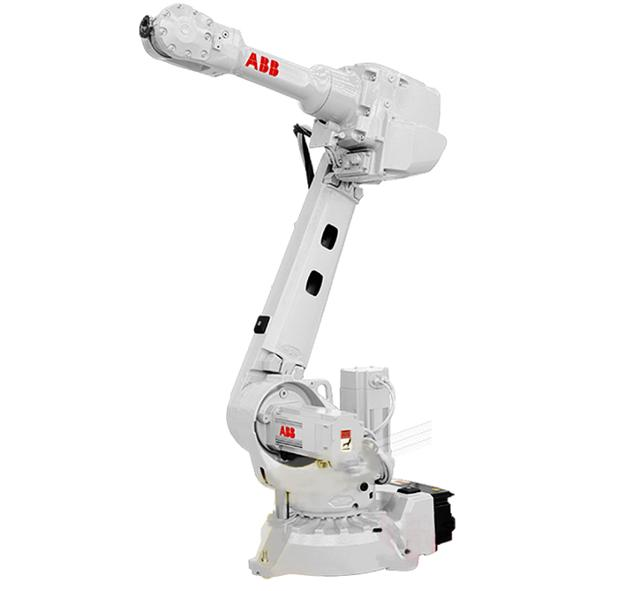
Industrial automated production line control: In industrial automated production lines such as automotive manufacturing and electronic equipment production, the AC 800F can be connected to a variety of fieldbus devices. By connecting robots, sensors and actuators through PROFIBUS – DP, the AC 800F achieves precise control of material handling, parts processing, product assembly and other aspects of the production line. Its high-speed data processing capability and configurable I/O scanning cycle can ensure the efficient and stable operation of the production line and improve production efficiency and product quality.

Process industry monitoring and control: In the chemical, petroleum, power and other process industries, the AC 800F is used for real-time monitoring and control of key parameters such as temperature, pressure, flow rate, etc. in the production process. Using its support for a variety of fieldbus types, such as Modbus, Foundation Fieldbus H1, etc., connected to various types of transmitters, control valves and other field equipment, to achieve accurate regulation of the production process. In chemical production, through real-time monitoring and control of reactor temperature and pressure, it ensures that chemical reactions are carried out under safe and efficient conditions, avoiding production accidents and improving product yields.

Smart factory construction: With the development of Industry 4.0 and smart manufacturing, AC 800F plays an important role as one of the core control equipment of smart factory. It integrates with other information systems in the factory to achieve real-time collection, analysis and sharing of production data. With the help of Ethernet communication and unified database, it transmits on-site equipment data to the management system, providing a basis for production decision-making. In the intelligent warehousing and logistics system, AC 800F controls the automated equipment for storing, sorting and transporting goods, improving logistics efficiency and reducing operating costs.

Critical Systems with High Reliability Requirements: The AC 800F’s redundant design plays an important role in areas that require high system reliability, such as aerospace and medical device manufacturing. Controller redundancy and Profibus line redundancy ensure that the system can operate normally in the event of a partial equipment failure. In aerospace manufacturing, where the precision of component processing and the stability of equipment operation are critical, the AC 800F’s redundancy feature ensures that the production process is not interrupted, avoiding production delays and quality problems caused by equipment failure.

ABB Freelance 800F AC 800F Control System

System Overview: ControlIT has evolved the control system into IndustrialIT, of which the AC 800F is a key part, seamlessly integrating processor-oriented information into open applications to improve process control using globally recognised industry standards. It has integrated fieldbus capability with 4 high-speed fieldbus lines and supports a wide range of fieldbus types, such as PROFIBUS – DP, Modbus, CAN, Foundation Fieldbus H1, and more.

Module introduction
Base unit: PM 802F and PM 803F with Super Scalar RISC microprocessors, different capacities of RAM and Flash – EPROM, temperature monitoring, watchdog, etc. Controller redundancy can be realised by installing two AC 800F.

Power supply module: SA 801F/SA 811F with 115 – 230V AC input, SD 802F/SD 812F with 24V DC input Redundant power supply, both of them can supply power to AC 800F module, with functions of over-voltage, over-current protection and power-down prediction.

Ethernet modules: EI 801F, EI 802F, EI 803F, EI 811F, EI 812F, EI 813F, etc., complying with IEEE802.3 standard, providing different interface types, supporting 10Base2, 10Base5, 10BaseT communication, and some of them are with battery back-up function.

Other modules: CAN-3 module FI 810F, serial module FI 820F, Profibus module FI 830F, FF/HSE module FI 840F are used to connect to different types of field buses, with corresponding communication rates, interface features and functions; battery module AM 801F provides battery backup for PM802F and AM 811F for AC 800F, ensuring data loss. The battery module AM 801F provides battery backup for the PM802F and AM 811F for the AC 800F, ensuring no loss of data.

Redundancy: Controller redundancy is achieved by installing two AC 800Fs, which are synchronised by means of a redundant communication link with a second Ethernet module; Profibus line redundancy can be achieved by using the redundant link module RLM 01 or a fibre-optic ring, which also allows for redundancy of both the controller and the Profibus line at the same time.

Compatibility: There are differences in compatibility between Control Builder F and AC 800F modules of different software versions, e.g. PM 802F for V6.1 and 6.2, PM 803F for V7.1, 7.2 and 8.1, and the functional characteristics of the different modules are different in different hardware configurations.
Technical parameters and environmental requirements: Each module has parameters such as rated voltage, power consumption, transmission rate, etc. The operating temperature of the system is 0 – 60°C, and the relative humidity is subject to a certain range. The product complies with a number of electromagnetic compatibility standards and electrical protection requirements, after vibration, shock test, the module power dissipation data can be used for cooling system calculations.

Design Advantage
Enhanced system reliability: controller redundancy, the installation of two AC 800Fs and the use of a dedicated redundant communication link of the second Ethernet module ensure that when the master AC 800F fails, the slave AC 800F can quickly and smoothly take over the work, and all the inputs and outputs support redundant operation, which greatly reduces the probability of system failures.

For example, in scenarios with high continuity requirements such as chemical production, controller redundancy can avoid production interruptions due to individual controller failures and reduce economic losses.Profibus line redundancyUsing the RLM 01 module to convert a non-redundant Profibus line into two redundant lines or adopting a fibre-optic ring network improves the reliability of the line and prevents line failures from affecting data transmission and equipment control.

Guaranteed data transmission stability: Ethernet communication redundancy is standard to ensure stable data transmission. In industrial environments, electromagnetic interference and other factors are prone to affect communication, Ethernet communication redundancy can avoid data loss or transmission interruptions, to ensure that the system’s real-time monitoring and control functions operate normally. cable redundancy for Profibus DP (requires external device RLM 01) further enhances the reliability of data transmission, and for a large number of devices in industrial sites relying on Profibus DP communication, it can For the large number of devices in industrial sites that rely on Profibus DP communication, this ensures accurate and timely data transmission between devices and maintains smooth production processes.

Supports continuous operation of the system: Device redundancy and power supply redundancy (24V DC) are designed so that the system can still work normally in the event of partial equipment or power supply failure. In some industrial production that cannot be easily shut down for maintenance, even if some of the equipment has problems, the system can still rely on the redundant equipment to continue to run, buying time for the maintenance of the faulty equipment and guaranteeing the continuity of production.

The module identification function records plant and operating parameters, which, together with comprehensive diagnostic functions, enables proactive maintenance, detects potential problems in advance, repairs them before they occur, and reduces the impact of sudden failures on system operation.

ABB 800xA for Harmony Systems

SYSTEM OVERVIEW: The 800xA for Harmony system interfaces with the Harmony Distributed Control System and integrates with the 800xA Operator Workspace to provide a unified view of operation and configuration.

Operator Interface – Panels: Harmony panels and associated point displays are an important aspect of Harmony tags. There are different panels for different tag types, such as Device Driver (DD), Multi-State Device Driver (MSDD), and so on. The panel is equipped with multiple functions, including monitoring, control, alarm display, etc., and has both general and specific functions to facilitate user operation and management.

Operation Parameter Setting: The Operation Parameter function allows you to monitor and change the status of Harmony tags and servers. Parameters are displayed in multiple tabs, such as the general tab showing basic tag information, the Harmony tab presenting network-related information, and the specific tag tab providing personalised data to meet different needs.

System Diagnostic Display: System diagnostic function is powerful, including cyclic topology, node topology and other display methods. Cyclic topology displays network node connections, node topology presents module details, and performance statistics and other functions to assist users in comprehensively understanding the system’s operating status and troubleshooting hidden problems.

Function module details: Block details function is used to check the function blocks in the controller, displaying their specifications, outputs and related information, and some specifications can be adjusted. Module details provide detailed operation status information for the controller or communication interface, including general information, status errors and problem reports, which facilitates an in-depth understanding of module operation.

SOE Reporting System: The SOE reporting system is used to accurately monitor changes in the status of key digital points. It supports a variety of functions, such as configurable trigger labels. The report collection and display mechanism is perfect, and the saved reports can be subsequently viewed and printed, making it easy to trace the sequence and cause of events.

Advanced Monitoring and Other Functions: The advanced monitoring function requires an additional licence and enables the monitoring of module status bytes and assessment of module conditions. The system also includes many other features, such as system status view, authentication management, log switching, etc., to ensure safe and stable operation of the system.

Server-related operations: The web-based Server Resource Manager provides access to diagnostic tools to view the status of servers, start, stop, and other operations. Replication Monitor is used to view the replication status of configured and connected servers and supports manual replication to ensure data consistency.

Application Cases
Power generation industry: In this industry, the 800xA for Harmony system accurately monitors and regulates various complex parameters in the power generation process by virtue of its powerful control capability. For example, it monitors the temperature and pressure of the boiler, as well as the speed and power of the turbine in real time to ensure the stable operation of the power generation equipment, improve the efficiency of power generation, and guarantee the reliable supply of electricity.

Chemical industry: The chemical production process is complex and requires high security and stability. This system can achieve comprehensive automatic control of chemical production process, real-time monitoring of temperature, pressure, liquid level and other parameters of the reaction kettle, and precise control of the flow and proportion of various chemical raw materials. When the system detects anomalies, it can quickly start the safety interlock mechanism to ensure production safety and reduce the risk of accidents, while optimising the production process and improving product quality and yield.

Pharmaceutical industry: Pharmaceutical processes are extremely demanding in terms of environmental and production parameters. 800xA for Harmony provides precise control of temperature, humidity, cleanliness and other environmental parameters in the pharmaceutical workshop to ensure that the production environment is up to standard. In the production process, it can accurately control the amount of various pharmaceutical raw materials and production process parameters, to ensure the stability and consistency of the quality of drugs, to help companies strictly follow the pharmaceutical production quality management standards.

Pulp and paper industry: The system plays an important role in the pulp and paper production line. It can automate the control of pulp consistency, flow rate as well as the speed and pressure of the paper machine and other key parameters to achieve precise control of the production process. This not only improves paper quality and production efficiency, but also reduces energy consumption and raw material waste by optimising the production process.

ABB Triguard SC300E MSR04XI

technical specification
Communication Specifications: Serial RS232 communication standard with 4 communication ports (Port 0 – 3) and 1 port for diagnostics only. Ports 0 – 3 support baud rates of 9600 or 19200 Baud, and ports 2 and 3 must be set to the same rate. The isolation of each port is up to 1kV, which can effectively prevent signal interference and ensure communication stability. The communication port adopts full-duplex mode, which can send and receive data at the same time, and the maximum communication rate is 19200 Baud, which meets the system’s requirements for data transmission speed.

Physical Specifications: The module is a 9U high printed circuit board (PCB) with integrated front panel and front and rear connectors. A plug-in daughter board carries the RS232 interface circuitry. The overall dimensions are 400 (9U) H x 397L x 28W (approx. 15.75H x 15.63L x 1.1W in.) and the weight is 1.3 kg. Mechanical coding blocks prevent the module from being inserted into the wrong slot and ensure accurate installation. 9 links are provided on the PCB, with each link having its own function, e.g., LK2 is used for module ID identification and must always be installed; LK3 is used for the 3 – 2 – 1 or 3 – 2 – 2 – 2 module. – LK3 for 3 – 2 – 1 or 3 – 2 – 0 operation mode setting, factory hardwired; LK4 for daughter board clock speed setting.

Environmental specifications: Operating temperature range of + 5°C to + 60°C, storage temperature range of – 25°C to + 70°C. Relative humidity requirements are between 5% and 95% and non-condensing at ambient temperatures below 40°C. The module has been tested and conforms to IEC 1131 and IEC 1131. Tested and compliant with IEC 1131 – Part 2 1994 standards for electromagnetic interference (EMC/RFI) immunity, as well as vibration and shock resistance.

Other specifications: The microcontroller is from the Intel family. The power consumption of the module is 3.5W, powered by dual redundant SC300E power supply units, with independent power supplies for the optical isolators and interfaces of the communication ports. It supports single-slot hot-repair and has a switch on the front panel for requesting the module to go offline. The front panel is also equipped with Tx, Rx, Health, and 3 On Line indicators to show the module’s working status.

Purpose: Provides a serial interface between the SC300E system and RS232-C compliant remote devices. At least one of these modules needs to be installed in Slot 10 of the main chassis to enable communication between the system processor and workstations for loading application software, monitoring ladder diagrams, and diagnostic functions. Additional modules can be installed in other I/O slots, with mechanical coding blocks to prevent misplacement.

Principle of operation: Data is fed into and out of the module via chassis backplane connector J1 and isolated from the MPP via the bus transceiver. When sending data, it is first loaded into the dual-port RAM, and then serialised and sent after 2 – oo – 3 votes; when receiving data, it is converted to parallel form by USART and written into the dual-port RAM, and then read by MPP. The communication port is an RS232 interface in full-duplex mode at a maximum rate of 19200 Baud, isolated from the module circuitry by an opto-isolator, and can drive a modem or line driver.

Maintenance and Service: Modules contain static-sensitive components and need to be shipped and stored in their original packaging. Failed modules are not repaired in the field and should be returned for service. Troubleshooting is performed using a TriBuild workstation and the faulty module health LED will go out. Take the module offline before removing it and take care to align the markings when inserting a new module. The module does not require preventative maintenance and spare parts and technical support are available from your local office.

ABB Triguard SC300E Triple Module Redundancy

Product Overview: Developed by August Systems and incorporated into ABB in 1997. It can be used as an engineered system or as an integrated product in a variety of applications such as safety shutdown and process control in the petrochemical, power and nuclear industries.

Product characteristics
High Availability: Modern low-power integration technology achieves up to 99.999% availability by maximising Mean Time Between Failure (MTTF) and minimising Mean Time To Repair (MTTR).
Ease of Use and Maintenance: Hardware and software integration, transparent to the user, with the lowest life cycle cost and support for online maintenance.

Fail-safe operation: Controllable failure modes for processor, input/output circuits, etc., defaulting to a safe state.
Fast Response: Scanning time resolution up to 10ms, suitable for high-speed control and event recording.
Fault Tolerance and Redundancy: Fully diagnostic and selective redundancy features to tolerate multiple non-concurrent faults and reduce false trips.
Transient Immunity: Physical and electrical isolation combined with asynchronous processors and software polling for immunity to transient errors.
Small footprint: ‘Plug and Play’ cabinet layout saves space and allows for easy cabling.

Hardware and Software Description
Hardware: Fully triple-redundant system architecture, including multiple chassis types, each with 10 slots for I/O modules and redundant power supplies. The processor is an Intel processor with a variety of storage and clock functions, and there are a variety of I/O modules with isolated signal paths, some of which support hot repair. There are also communication modules and various types of field terminal cards.

Software: Supports TriBuildTM, TriCommandTM and TriLogTM Windows-compatible software. TriBuild is used to develop and programme application logic; TriCommand provides real-time system control and monitoring; and TriLog is used for logging events and alarm messages.
International standards: ABB’s quality system complies with international standards and is certified according to a number of certifications, such as BS EN ISO 9001 1994. products meet the requirements of many international standards and are subject to thorough testing and control.

Applicable Scenarios
Industrial production safety protection: In petroleum, chemical and other industries, it is used for safety shutdown, process shutdown and emergency shutdown systems. For example, in oil refineries, when abnormal conditions occur, such as temperature and pressure exceeding the safety range, Triguard SC300E can react quickly and start the shutdown procedure to safeguard personnel, equipment and products and prevent the accident from expanding.

Stability control in the energy sector: In power systems, for electrical stability and load control. It ensures stable operation of the power grid under different working conditions, avoids power fluctuations caused by sudden load changes and other problems, and guarantees the reliability of power supply. In power plants, it is used for turbine and compressor control to optimise equipment operation and improve energy conversion efficiency.

Precise control of complex processes: It is suitable for critical batch, sequence and interlock control as well as critical process control. In pharmaceutical, food processing and other industries with strict requirements on the production process, it can precisely control the production process to ensure the consistency and stability of product quality. For example, in pharmaceutical production, the temperature, pressure and time parameters of each production process are controlled in strict accordance with preset procedures.

ABB REB500 REB500sys Digital Substation Protection System

Product Overview: The REB500/REB500sys are fully digital protection devices, based on the INX2 and INX5 analogue electronic busbar protection schemes. The compact design, the small number of hardware units, the modularity of the software, the self-monitoring and diagnostics make them suitable for a wide range of busbar layouts and power systems, and they are capable of detecting a wide range of faults and integrating a wide range of optional functions.The REB500sys additionally includes an interval protection function.

Safety instructions: The degree of danger is marked by different symbols, e.g. ‘DANGER’, ‘WARNING’, ‘NOTE’. Emphasis is placed on following the safety rules and operating the equipment only when it is normal and used in strict accordance with the operating instructions, and there are strict requirements for the qualification of the operating and maintenance personnel.

Basic system concept: Introduces the scope of application, system capacity, structural composition (including central unit, interval unit, etc.), hardware modules, software system, signal acquisition and processing, basic functions of self-monitoring and protection system, and busbar protection functions. For example, the system supports up to 60 interval units and 32 protection zones; protection functions are realised through a variety of measurement principles and logic.

Human-machine interface (HMI500): It is used to interact with the protection system, and can realise operations such as checking the measurement status, setting the protection function and configuring the system. It introduces its installation requirements, operation methods, functions of each menu and common error message processing, such as viewing all kinds of measurement data and configuring system parameters through different menus.

Configuration and Setting: system configuration and parameter setting with the help of HMI500, covering equipment activation/deactivation, various equipment parameter changes, binary module configuration, event text setting, interference recorder configuration, etc. It also introduces the calculation and setting methods of system response, busbar protection and other parameters.

Installation and commissioning: including equipment transport, storage and installation precautions, such as grounding, wiring, shielding requirements; a number of checks need to be carried out before commissioning, test and configure the system in accordance with the process, and add or remove intervals also have corresponding operating procedures.

Specification
Hardware Configuration: The central unit is 19’ cased and can accommodate up to 20 hardware modules, including a variety of functional modules, such as Master CPU (500CPU05), Slave CPU (500CPU05), etc. The spacer unit is available in different versions, such as 500BU03, with a variety of measurement and input/output capabilities, and supports redundant power supplies. The spacer units are available in different versions, e.g. 500BU03, with a wide range of measurement and input/output capabilities, and support redundant power supplies.

Electrical parameters: Power supply input voltage range 36V DC – 312V DC, outputs for various standard voltages, CT input supports 1A and 5A rated currents, VT input rated voltage 200V, A/D converter resolution 16Bit, sample rate varies at different system frequencies.
Functional parameters: Supports up to 60 spacers and 32 protection zones. Various protection functions are available, such as busbar protection, circuit breaker failure protection, etc., and each protection function has a corresponding parameter setting range.

Performance Advantages
High reliability: Double independent criteria, i.e. differential current with braking characteristics and directional current comparison, are used to evaluate each phase independently and to distinguish between internal and external faults effectively. Equipped with comprehensive self-monitoring and diagnostic functions, it can monitor the hardware and software status in real time.
Strong adaptability: applicable to a variety of busbar layouts, such as single busbar, double busbar, etc., can adapt to different power system grounding methods, low requirements for CT performance, even if the CT is saturated, it can also operate stably.

Feature-rich: integrates a variety of protection functions, and can also be extended with optional functions, such as voltage measurement interference recorder, independent I0 measurement, etc. Friendly man-machine interface for easy operation and monitoring.

Trial Scenarios
Power substations: Can be used in 50 Hz and 60 Hz medium-voltage (MV), high-voltage (HV) and extra-high-voltage (EHV) substations to provide protection for busbars, lines and transformers.
Railway systems: for railway power supply systems up to 16.7 Hz to ensure a safe and stable railway power supply.
Complex power grids: In complex power grid structures such as bypassed busbars and ‘tandem bus contact’, it can effectively realise the protection function and adapt to different operation modes.

ABB Distributed busbar protection REB500

Product Overview: REB500 is a digital busbar protection device for high-speed, selective protection of medium-voltage (MV), high-voltage (HV) and ultra-high-voltage (EHV) busbars, on which REB500sys integrates line and transformer protection functions, suitable for a variety of busbar configurations and power supply systems.

Main features: low impedance busbar protection technology, with dual independent measurement standards, phase-to-phase measurement, low performance requirements for current transformers (CT), and high resistance to CT saturation. There are centralised, distributed and hybrid installation modes, connected by optical fibre, data transmission is anti-interference and easy to expand. With user-friendly PC human-machine interface (HMI), comprehensive self-monitoring functions, integrated event and disturbance records, low spare parts requirements, support for a variety of communication protocols.

Application Scenario: Suitable for 50Hz, 60Hz and 16.7Hz MV, HV and EHV substations, protecting various busbar configurations and line and transformer feeders. A wide range of fault types can be detected, and protection schemes can be simplified or optimised according to different network voltage levels and protection concepts.

System design: consists of a spacing unit (500BU03) and a central unit (500CU03). The interval unit is responsible for data acquisition, pre-processing, control and interval protection functions, is electrically insulated, can operate independently, and has a variety of analogue inputs and binary I/O configurations; the central unit serves as the system manager and is responsible for the system configuration, data processing, and communication control, and the modules have plug-and-play functionality.

Functions: Busbar protection is based on stable differential current measurement and directional current comparison algorithms for fast and accurate fault detection. It also has various functions such as circuit breaker failure protection, terminal fault protection, overcurrent protection, etc., which can ensure the reliability and selectivity of the protection action through a variety of criteria and logic. The event and disturbance recording function can record the system operation data in detail, and the communication interface supports various protocols, which is easy to integrate with the substation monitoring system.

Technical data: There are clear requirements for fibre optic cables, isolator auxiliary contacts, circuit breaker replicas and main CTs. The products meet the relevant standards in terms of temperature, climate, electromagnetic compatibility, etc., with detailed technical parameters of hardware and software modules, such as analogue inputs, binary I/O, auxiliary power supply, etc.

Connection diagrams and installation: Connection diagrams for the central unit and the spacer units are provided, showing how the various input and output interfaces are connected. The products are available in different mounting versions, with clear mechanical design parameters such as dimensions and weights of the spacer units and the central unit, as well as corresponding specifications and requirements for cabinet mounting.

GE Multilin 239 Motor Protection Relay

Data format and rate
Data frame format: Asynchronous transmission data frame consists of 1 start bit, 8 data bits and 1 stop bit, total 10 bits.

Data Rate: Supports 1200, 2400, 4800, 9600 and 19200 baud rates.

Packet Format: Contains slave address, function code, data and CRC check code, the packet format of master request and slave response are similar.

Error checking: CRC-16 (16-bit Cyclic Redundancy Check) algorithm is used to check for transmission errors, if there is a checksum error, the slave will not respond.

Timing: The receiving device maintains packet synchronisation by measuring the time between character receipts. If no new character is received for more than 3.5 characters or the packet has not been received, the communication link is reset.

Supported Modbus Functions
Reading of set and actual values (function code 03/04): The set (‘Holding register’) and actual (‘Input register’) values of the relay can be read, up to a maximum of 125 registers at a time, with the data being transferred in two bytes, the lower byte first. The data is transferred in two bytes, with the lower byte first.

Execute operation (function code 05): The master can use this function to request the relay to perform a specific command operation, which corresponds to the command code in the memory map.

Storing a single setpoint (function code 06): the master stores a single setpoint in the relay memory and the slave response displays the entire master transfer.

Read device status (function code 07): Used to quickly read the status of the selected device, each bit of the returned status byte indicates different status information.

Loopback test (function code 08): Used to test the integrity of the communication link, the relay displays the request.
Storing multiple setpoints (function code 16): multiple setpoints can be stored in the relay memory, Modbus allows up to 60 holding registers to be stored at one time, the slave response will display the relevant information.

Performance Advantages
Comprehensive protection functions: Thermal overload (15 selectable curves), phase short-circuit, mechanical fault, thermal memory blocking, single-phase/current imbalance, earth fault (trip and alarm), over-temperature (via thermistor or optional RTD input), under-current, circuit breaker failure, etc., which can provide all-round protection for motors and related mechanical equipment, and effectively respond to all kinds of electrical and mechanical faults.

Compact and cost-saving design: The compact design reduces installation costs, which is more advantageous in space-constrained installation environments.

Flexible settings: With multiple setting groups, the protection and control parameters can be flexibly adjusted according to different application scenarios and motor requirements to meet diversified usage requirements.

Convenient testing: Built-in simulation function simplifies the testing process and facilitates testing and debugging of relays in the field, which reduces maintenance time and cost.

Powerful equipment monitoring: Real-time temperature monitoring through optional RTD input can detect motor overheating problems in time, and display status, current, temperature and other information, with fault diagnosis, trip records (the last 5 times) and other functions, so that operators can easily understand the operating condition of the equipment, and troubleshooting in time.

Convenient communication and upgrading: It supports Modbus RTU communication protocol, which is convenient for data interaction and remote control with other equipments; it can be upgraded on site by using flash memory, which can follow the pace of technological development and keep the advanced performance of the product.

Product Specification
Communication protocol: support Modbus RTU protocol, to ensure the compatibility and stability of communication with other devices.

Control power supply: DC control power supply input range of 90 – 300Vdc, can adapt to a variety of power supply environment.

Overload protection: Locked rotor start protection range is 0.5 – 11.0 xflc; overload curve trip time pickup level is 1 – 1500A.

Other accuracy specifications: Thermistor accuracy is ±5% or 100Ω (whichever is greater); unbalance accuracy is ±2%.
Switch input type: Dry contact switch input.

Physical Characteristics: Approximate shipping weight of 5 lbs. or 2.3 kg, compact design, fits most starters.

User Interface: RS485 serial interface, keypad, 40-byte backlit display, 6 LEDs, and compatibility with Enervista setup software for easy parameter setting, status viewing, and control.

GE 169 MOTOR MANAGEMENT RELAY

Product overview
Protection requirements and functionality: Modern three-phase AC motors require precise protection and the 169 Relay has been developed for this purpose. It thermally models the motor’s phase currents and stator RTD temperature readings, takes into account the effects of negative sequence currents, calculates cooling times and monitors faults.

With overload, short circuit and earth fault protection, as well as monitoring, diagnostic and communication features, the 169 Plus is even more versatile.

Typical applications: Suitable for a variety of scenarios, such as protecting motors and equipment, ensuring personnel safety, monitoring equipment operating status, and communicating with control systems.

Technical specifications: The measuring range, accuracy, conversion method and other performance indexes of the relay for various parameters such as phase current, ground fault current, etc., such as the accuracy of overload curve tripping time and relay locking time.

Installation Guide
Physical dimensions and installation: the relay is compact, the installation needs to pay attention to the position and direction, the installation dimensions and methods are provided, and electromagnetic interference should be avoided .

External Connection: Connections include power supply, CT, RTD, and other inputs and outputs, which vary by model and function, and should be connected as required.

Control power supply: AC and DC voltages are available, AC voltage is selected by slide switch, make sure the voltage is correctly selected during installation, and the control power supply should be connected and programmed before the motor is started.

Setup and Use
Control and Display Mode: Operated by 12-digit keypad and 48-character display, there are four modes: actual value, set point, help and trip/alarm, which can view and set motor operating parameters, relay protection settings and other information.
Parameter setting: In setpoint mode, various parameters can be set, such as phase CT and motor full load current, acceleration time, number of start-ups, etc. When setting, it is necessary to pay attention to the range of parameters and the relationship between them.

Special functions: thermal memory function, can adjust the overload protection according to the motor running status; emergency restart can be forced to restart the motor under specific circumstances; the relay also provides statistical data records and factory preset values.

Relay Testing
Test Methods: Includes primary and secondary injection tests to check relay functions such as phase current input, ground fault current, RTD measurement, etc.

Routine Maintenance Verification: Periodic testing checks the protection system by simulating fault conditions to ensure that the relay is functioning correctly and that setpoints are restored after testing.

Working Principle
Hardware: Controlled by the 8031 microcomputer, it consists of several circuit modules such as power supply, signal processing, temperature monitoring, etc., which work together to realise the relay functions.

Firmware: Programmes stored in the EPROM control the mathematical, logical and control functions of the relay, performing various tasks such as data acquisition, fault judgement, display update, etc. through timed interrupts.

caveat
Mounting Environment and Physical Installation: The relay should be mounted in a location where the display is visible and the keypad is operable, and away from high current conductors or sources of strong magnetic fields to reduce electromagnetic interference.

Cut appropriately sized openings in the mounting panel as required and secure using the supplied mounting hardware. If using a 169 drawout relay, pay attention to the sequence of operations during installation and removal to prevent unintentional motor shutdown and risk of electric shock.

External Connections: The type of connection depends on the programming of the relay. Basic connections include power, three-phase current CT inputs, and trip relay contacts. When connecting, pay attention to the polarity and phase sequence of the CTs to ensure that the earth fault CTs are correctly installed, all current carrying conductors need to be routed through the earth fault CTs and the safety earth wire should be outside the CT window.

Output relays of different functions (e.g. trip, alarm, auxiliary relay, etc.) have different connection requirements and rated loads, and should be connected in strict accordance with the regulations.

Control power supply: The control power supply has a variety of voltages to choose from, the AC voltage is selected by a slide switch, before installation make sure that the switch is set correctly and that the control power supply label is consistent with the selected voltage.

The control power supply must be connected to the relay and programmed before the motor is energised. Also note that the chassis earth terminal should be connected directly to a dedicated cabinet earth conductor to prevent damage to the relay due to changes in earth potential.

Other considerations: When connecting RTD sensors, all RTDs must be of the same type, and the connecting wires should be shielded three-wire cables of the same length with resistance not exceeding the specified value, avoiding parallel laying with high-current wires.

If RTD #8 (RTD #10 for 169 Plus) is used to monitor ambient temperature, it needs to be properly selected and installed. Programming access terminals should be disconnected after programming is complete or safety measures should be taken to prevent inadvertent change of setpoints.

GE 139 SERIES MOTOR PROTECTION RELAY

Product Overview
Functional features: All-round protection of three-phase AC motors, with overload, blocking, single-phase/unbalance, ground fault and other protection functions, but also diagnose faults, emergency restart and verification of relay operation status.

Application Scenarios: Suitable for a variety of industrial scenarios, such as pumps, fans, compressors and other equipment protection, can prevent equipment failure caused by personnel safety issues and equipment damage.
Relay selection: Horizontal and vertical mounting versions are available, depending on the application requirements and the type of current transformer (CT) (1A or 5A). Some features are optional and must be specified at the time of ordering.

Installation Guide
Physical dimensions and mounting: The relay is housed in a high-impact plastic case with a dust cover. The mounting is recessed and secured to the panel by U-clips. Check the options and switch settings on the product specification card before mounting.

External Connections: Connections include power supply, CT input, main relay contacts, etc. Some connections are optional. The power supply has two options, AC and DC, and the CT secondary side needs to be grounded.
CT Connection: One CT is required for each phase of the motor, and the secondary side of the CT should match the current of the relay. 5A CT has a specific connection method, and 1A CT can be adapted to the 5A CT design of the relay by changing the wiring method.

Other connections: earth fault CT for earth fault detection, main and auxiliary relay contacts for control and alarms, external reset and emergency restart functions can be realised with specific terminals, options such as temperature sensing, thermal capacitance meter and current outputs have corresponding connections.

Setup and use
Control and Indication: Parameters are set via the front panel control. Indicator lights are used to show the operating status of the relay and fault information.

Parameter setting: including maximum load control, unbalance control, undercurrent control, start timer setting, etc. Each parameter should be adjusted according to the actual situation of the motor.

Function options: Programmed by internal selector switch, such as cyclic overload compensation, immediate overload warning, emergency restart, memory function, etc., which can be switched on or off according to the application requirements.

Special functions: Ground fault protection can be set with different trip currents and delay times; over-temperature protection is realised by RTD sensors, which can be set for alarm and trip temperatures; the thermal capacity meter and 4 – 20mA output function are optional for easy monitoring and control.

Relay Testing
Test equipment: Commercial secondary injection test equipment or homemade test circuits can be used to test relays.

Test Items: Including overload, start timer, unbalance, undercurrent, ground fault, over-temperature and other functional tests, the test should pay attention to simulate the actual working conditions and operating specifications.

Daily maintenance verification: Regular testing can check the correct operation of the protection system, simulate various fault conditions for testing to ensure that the relay works properly.

Troubleshooting: Possible causes and solutions are provided for common fault symptoms, such as relays failing to reset, frequent overload trips, and so on.

Working Principle: Each phase current is isolated and converted by CT, then sampled and amplified by electronic switch. Fault judgement such as overload, unbalance, undercurrent is achieved by comparing with preset reference value. Overload timing is controlled by an integrator circuit with different charging rates in start-up mode. Alarm functions are implemented by separate relays, with separate detection and comparison circuits for RTD and earth fault alarms.

Search for products

Back to Top
Product has been added to your cart