Call us 24/7uaedcs@163.com
Welcome to the official website of CNIACS Automation Technology Co., Ltd!
Call us 24/7uaedcs@163.com

AB Stratix 8000 and 8300 Ethernet Managed Switches

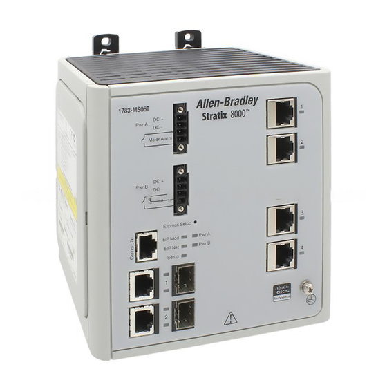
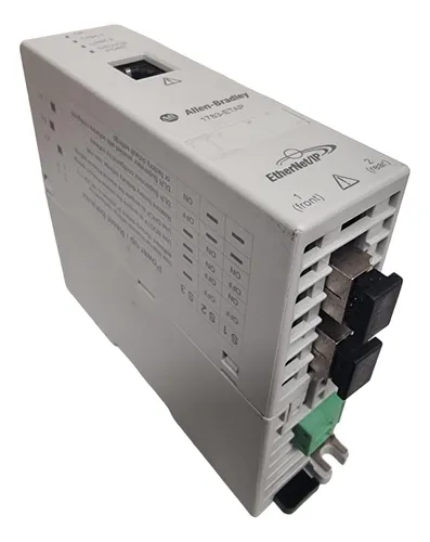
Product Overview: The Stratix 8000 and 8300 Ethernet Managed Switches are designed for use in harsh industrial environments, connecting servers, routers, PLCs, and other network devices. They are available in models such as the 1783-MS06T (4 10/100BASE-T Ethernet ports and 2 dual-purpose ports) and 1783-MS10T for the Stratix 8000 series, and the 1783-RMS06T and 1783-RMS10T for the Stratix 8300 series. There are also expansion modules 1783-MX08T (8 10/100BASE-T copper Ethernet ports), 1783-MX08F (8 100BASE-FX fibre-optic Ethernet ports), and a variety of SFP modules.

Preparation for installation: Before installation, make sure that the installation environment meets the requirements, the ambient temperature is between -40°C and 60°C, and there is enough space around the equipment to ensure that the airflow is not blocked. Prepare tools such as a ratcheting torque screwdriver and specific copper grounding wire.

Installation Procedure:
Connection of expansion modules (optional): 1 – 2 expansion modules can be installed, with specific combination limitations, remove the side panels before installing and fixing.
Mounting the switch: DIN rail, wall or panel mounting is available; DIN rail mounting requires attention to grounding and DIN rail type; wall or panel mounting requires specific bolts and washers.
Mounting SFP Modules (optional): wear an ESD wrist strap during operation and be aware of module compatibility.
Grounding: Use 5.3 mm 2 (10 AWG) grounded copper wire to connect to the ground screw on the front panel of the switch.
Connecting the DC Power Supply: The power supply must comply with the CE Low Voltage Directive and UL limits, observing positive and negative polarity and torque requirements when connecting.
Connecting the power supply and relay connectors: Insert the connectors and tighten the screws, taking care to isolate the voltages if more than one power supply is used.
Connecting external alarms (optional): connect up to two external alarm devices, use specific wires and pay attention to voltage and torque requirements.

Configuration Management:
Express Setup: Used to set the initial IP address, requires specific device and network configuration.
Configuration Management Methods: Configuration and management can be performed through the Device Manager web interface, RSLogix 5000 software, and other methods.
Reset Operation: The switch can be restored to the factory default settings, after which it needs to be reconfigured.
Troubleshooting: Faults such as POST failure, port connection problems, etc. can be determined by the status indicators on the front panel of the switch. Troubleshooting can also be assisted by obtaining statistical information through the browser interface, command line interface, or SNMP workstation.

Product Specifications
Electrical specifications: The input voltage range is 18-60V DC and the maximum input current is 1A, which can adapt to power fluctuation within a certain range and provide power protection for the stable operation of the switch. The alarm relay is rated at 30V DC max. and 1A max. and can be used to connect external alarm devices to issue an alarm in time when the system is abnormal. For isolation voltage, the switch base and expansion modules have specific isolation requirements between different ports, such as 75V (continuous) basic insulation type between DC power port and ground, Ethernet port, alarm port, and between Ethernet port and expansion backplane, and have been tested at 1000V AC 60s, which guarantees electrical isolation between different circuits and improves the system security .

Physical Specifications: The dimensions of the switches and expansion modules are clearly defined, taking the 1783-MS10T and 1783-MX08T as examples, which facilitates space planning and layout during equipment installation. A variety of port types, including 10/100BASE-T, 10/100/1000BASE-T copper ports and SFP module slots, as well as 100BASE-FX fibre-optic ports (only available on the 1783-MX08F expansion module), are available to meet the connectivity needs of different devices. The connecting wires have specific specifications, including IEC 60603-7-compliant RJ45 connectors and at least Category 5e cables for Ethernet connections, 0.5-0.8 mm 2 (20-18 AWG) copper wires for DC power and alarm connections, and 3.3-5.3 mm 2 (12-10 AWG) copper wires for functional ground connections, ensuring the reliability of the electrical connections. Ensures reliable electrical connections.

Environmental specifications: Operating temperature range of – 40°C to 60°C and non-operating temperature range of – 40°C to 85°C provide a wide range of temperatures for stable operation in a variety of climatic and industrial environments. Relative humidity requirements of 5% to 95% non-condensing, even in humid environments. The product is IP20 rated, which provides a degree of protection for the internal circuitry by preventing the ingress of solid foreign objects larger than 12mm. There are also standards for vibration and shock, such as 2g @ 10-500Hz for vibration, 20g for operating shock, and 30g for non-operating shock, providing strong resistance to environmental interference.

Performance Features
Port auto-negotiation and self-adaptation: The ports are equipped with the functions of auto-negotiation of link speed (10 Mbps or 100 Mbps) and duplex setting (full-duplex or half-duplex), which can automatically match the optimal network connection parameters with the connected devices without manual configuration, thus improving the convenience and compatibility of device connection. Some models of dual-purpose ports, in the SFP module port and RJ45 port at the same time there is a connection, the SFP module port has priority, this design makes the network connection more flexible, according to the actual needs of the choice of different connection methods.

Multiple Configuration and Management Methods: Provides multiple configuration and management methods, including Device Manager web interface, RSLogix 5000 software, Cisco Network Assistant, Command Line Interface (CLI) and SNMP management application. Users can choose the appropriate way according to their own needs and technical level, which is convenient for initial setup, daily management and troubleshooting of the switch. The Express Setup function allows users to quickly set up the initial IP address of the switch, enabling the switch to be connected to the network for subsequent management and simplifying the configuration process during initial use.

Fault Detection and Indication: The status indicators on the front panel can visually reflect the working status of the switch, including power status (PWR A, PWR B indicators), EtherNet/IP module status (EIP Mod indicator), network status (EIP Net indicator), setup status (Setup indicator), and port status (Port indicator, etc.). By observing the colours and flashing status of the indicators, users can quickly determine whether the switch is working properly and find and locate faults in time, such as POST failure, port connection problems, etc. The switch will perform POST at startup. The switch will perform POST (power-on self-test) at startup, if POST fails, the system status indicator will turn red, which indicates that there is a fault in the device and it needs to be checked and repaired accordingly.

AB 1783 Series Ethernet Taps

Preparation before installation:
Safety and environment: the use of equipment has special conditions, the application of hazardous areas need specific protection, should be installed in the enclosure in line with the requirements of the industrial environment for pollution degree 2, belongs to the A class of industrial equipment, installation and operation of professional personnel in accordance with the norms. The equipment is sensitive to static electricity, and anti-static measures should be taken during operation.

Networking and Grounding: For use in linear or star networks, ensure that Ring Supervisor mode is not enabled; in DLR networks, consider whether the tap acts as a ring manager. The product should be mounted on a well-grounded surface, recommended DIN rail in galvanised yellow chromate steel, fixed at approximately 200mm intervals.
Installation procedure:

Mounting method: Panel mount or DIN rail mount is optional, 2.54cm gap should be left on each side of 1783-ETAP module; 7.62cm gap should be left on the bottom of 1783-ETAP1F and 1783-ETAP2F module, 2.54cm gap should be left on the other sides, and the bending radius of the fibre optic cables should be at least 5.08cm.

Wiring operation: Provide 24V DC power through the DC connector, follow the relevant electrical safety standards, and connect no more than two wires per terminal. When connecting the RJ45 port, follow the steps to connect the device and the network; when connecting the optical fibre ports of the 1783-ETAP1F and 1783-ETAP2F, be careful to avoid looking directly at the optical ports.

Software and Configuration:
Software Requirements: RSLinx Classic 2.56.00 or higher, Studio 5000 Logix Designer 21.00.00 or higher software is required.

IP Settings: The default IP address of 169.254.1.1 can be used or configured through RSLinx Classic software, Studio 5000 Logix Designer application, or obtained from a DHCP or BOOTP server.
DIP Switch Settings: DIP switches can be used to select IP setting method, enable Ring Supervisor mode, restore factory default settings, etc.

Status Monitoring and Diagnostics:
Status Indicators: The status indicators of 1783-ETAP, 1783-ETAP1F, and 1783-ETAP2F have similar meanings; different statuses of OK indicator indicate different working conditions, and LINK1 and LINK2 indicators reflect the link status.
Web Interface Diagnostics: The tap supports a web interface that provides diagnostic information, including module resource utilisation, network settings, Ethernet statistics and ring statistics.

Performance Features
Port Auto-negotiation: By default, each port of the 1783-ETAP module is able to auto-negotiate the link speed (10 Mbps or 100 Mbps) and duplex setting (full duplex or half duplex), which enables the module to quickly adapt to different network environments and establish a stable connection without the need for users to manually carry out complex settings, improving the ease of use and compatibility of the device. The module supports a variety of network configuration methods.

Supports multiple network configuration methods: The module supports multiple network configuration methods, users can either use the default IP address 169.254.1.1, by connecting the module directly to the computer and setting the IP address on the same subnet (e.g., 169.254.1.2) in the computer’s Local Connection Properties to communicate; or through the RSLinx Classic software, Studio 5000 Logo, or the RSLinx Logo. IP settings can also be made using RSLinx Classic software, Studio 5000 Logix Designer application.

Allen-bradley 1783-etap2f - Taps Ethernet/ip De 1+2 Portas | MercadoLivre

AB 1771 Digital I/O AC Input and Output Modules

General information about the modules:
Product Family: Part of the Digital I/O product family, which consists of AC input/output, DC input/output, and relay contact output modules.

System Compatibility: Each module has specific compatibility with different models of 1771 I/O chassis and processors, and the way data tables are used varies by module.
Status Indicators and Keypads: Status indicators on the front panel of the module indicate input or output status, and some have additional indicators; plastic keypads ensure that the module is properly installed in the I/O slot.

Power Requirements and Layout: Modules draw power from the backplane of the 1771 I/O chassis, and the total current should be calculated to prevent overloading. Module layout should be considered to reduce electromagnetic interference and thermal effects, and analogue inputs and low voltage DC modules should be located away from AC or high voltage DC modules.

Product Specifications
Input Module Specifications: Input voltage range is wide, such as 1771-IA series C and 1771-IA2 modules rated input voltage is 120Vac @47 – 63Hz, 125V dc, and 1771-IAD series D module is 120V ac@ 50/60Hz, 125V dc, which varies from module to module according to its own characteristics. As for the input current, the current value varies with different voltages, like 6.83mA at 120Vac 50Hz for 1771-IA series C. The input signal delay also varies from module to module. The input signal delay also varies from module to module, ranging from a few milliseconds to tens of milliseconds. In addition, each input module has a different number of input channels, such as 8 channels, 16 channels, 32 channels, etc., to meet different application requirements.

Output Module Specifications: Output voltage ranges vary from 92 – 138V ac @ 47 – 63Hz for 1771-OA Series B Modules to 184 – 250V ac @ 47 – 63Hz for 1771-OMD Series B Modules. Output current ratings also vary, such as 1.5A per output (up to 6A total) for 1771-OA Series B modules and 2A per output (up to 6A total) for 1771-OD Series C modules. The output modules also have different inrush current, load current minimum, on-state voltage drop, off-state leakage current, and other parameters that determine the performance of the modules under different load conditions.

Performance Features
Electrical isolation and protection: All modules are equipped with electrical-optical isolation to effectively protect the backplane circuits, module logic circuits and the entire system from electrical transients. Some output modules are also equipped with surge suppression circuits, such as metal-oxide varistors (MOVs) and RC networks at the output terminals, to suppress high-voltage transients and limit the magnitude of voltage transients, thus prolonging the service life of the equipment.

Status Indication and Troubleshooting: The front panel of each module is equipped with status indicators, which clearly show the ON/OFF status of inputs or outputs, and some modules are also equipped with additional indicators such as blown fuses and thyristor failures, which are convenient for users to discover and troubleshoot in time, quickly identify system problems and improve system maintenance efficiency.
Flexible Failure Mode Selection: Some of the digital AC modules allow users to select the failure mode by configuring jumpers, and inputs or outputs can be set to remain in the last state or reset to off in case of a failure, which enhances the flexibility and reliability of the system, and meets the needs of different application scenarios for fault handling.

Application Scenarios
Industrial automation production line: In industrial production, various types of sensors (e.g. proximity switches, limit switches, etc.) and actuators (e.g. motor starters, solenoid valves, etc.) can be connected to achieve precise control of the production process. In the automobile manufacturing line, it is used to monitor and control the position and movement of the robot arm to ensure the accurate assembly of parts; in the material conveying system, it is used to control the starting and stopping of the conveyor belt motor to realise the automatic transport of materials.

Mechanical equipment control: It is applicable to the electrical control of various mechanical equipment, such as injection moulding machines, CNC machine tools and so on. In the injection moulding machine, it controls the opening and closing of the mould, the execution of the injection action, and the monitoring of the running status of the equipment; in the CNC machine tool, it receives the operating instructions and controls the operation of the motor to achieve the precise movement of the tool and the automation of the machining process.

Automated Warehousing System: In automated warehousing equipment, such as stacker cranes, shuttle cars, etc., it is used to control the movement and positioning of the equipment, as well as the gripping and placing operations of the goods. By cooperating with sensors, the precise operation of the equipment can be realised, and the working efficiency and accuracy of the storage system can be improved.

AB 1771-VHSC Very High-speed Counter Module

Preparation before installation:
Static protection: touch a grounded object when handling the module, wear a wrist strap, avoid touching the backplane connectors and internal circuitry components, and place in a static-shielding bag when not in use.

Directive Compliance: CE-marked, compliant with EU EMC and Low Voltage Directives and meets relevant standards.
Power Calculation: The module draws power from the 1771 I/O chassis backplane at a maximum current of 650mA (3.25W), which is required to calculate the total power in the chassis to prevent overloading.
Installation Procedure:

Jumper Setting: Each input channel has jumpers for filter/high speed operation, +5V or + 12 – 24V operation, 6 in total, which can be set independently. High-speed mode is suitable for encoders and other devices, and filter mode is used for electromechanical switch inputs (frequencies greater than 100Hz are not detected).
Module Installation: It can be installed in other slots except the leftmost slot, and different addressing modes have different requirements for module groups. The keyed strips are mounted on the backplane between 24 – 26, 28 – 30. To install, disconnect power, insert and secure the module, and connect the 1771-WN wiring arm.
Wiring Connections: Disconnect power before connecting I/O devices, shield sensor cables and ground only at the chassis end.
Grounding: Using Belden 9182 cable, follow the steps for cable handling and grounding, taking care to install a washer and nut when connecting the grounding conductor.

Module Configuration:
Operating modes: 6 modes: Counter mode, Encoder X1 mode, Encoder X4 mode, Cycle/Rate mode, Rate/Measurement mode, Continuous/Rate mode. For example, the counter mode is used to read pulses from up to 4 devices such as encoders; the encoder mode is used to process orthogonal pulses.
Gate/Reset Inputs and Stored Counts: Gate/Reset inputs can scale pulses, there are 4 stored counting modes that can be triggered on rising or falling edges, and stored counts can be updated by related events in specific modes.
Output Settings: Outputs can be connected to any counter input, have on and off presets, and represent frequency values in Rate Measurement mode (up to 500,000Hz).
Status and diagnostics:

Data Acquisition: The PLC processor acquires the module status and input data through the BTR instruction, which transfers up to 26 words and returns 18 words when the programmed BTR is zero.
Troubleshooting: The module returns diagnostic information in word 1 of the BTR file, including power supply, data update, and error codes. The status indicator can indicate the working status of the module, such as ACTIVE light indicates that the module receives power and operates normally, while FAULT light indicates that the module needs to be investigated according to the steps.

Specification
Electrical Performance Parameters: The maximum input frequency of the module varies depending on the mode of operation, up to 1MHz in counter mode (single channel), 250kHz in encoder mode (2-channel quadrature), 500kHz in cycle/rate, rate/measurement, and continuity/rate modes, and 100Hz in filtering mode for processing electromechanical switching inputs. Input voltages of 5V or 12 – 24V are supported and can be selected by the user according to actual requirements.

Outputs are available from 5 – 24V (customer supplied) with output currents of 2A per channel and all outputs can be switched on simultaneously without derating. Output control is flexible, any number of outputs can be assigned to any of the 4 counter channels, and each output also has an ‘on’ preset and an ‘off’ preset respectively.
Environmental Adaptation Parameters: In terms of operating temperature, the module has an operating temperature range of 0 – 60°C (32 – 140°F), a storage temperature range of – 40 – 85°C (- 40 – 185°F), and a relative humidity requirement of 5 – 95% (non-condensing). These parameters define the environmental conditions under which the module can work stably. Users should ensure that the ambient temperature and humidity are within the specified range when using the module in order to avoid any degradation of performance or failure of the module due to environmental factors.

Other Parameters: The module occupies one slot in the 1771 Series A or B I/O chassis and has a programmable maximum count value of 0 – 999,999. The BTW processing time is 5.5ms in the worst case (binary and with configuration changes) and 1.5 – 2.9ms typical. The electrical isolation of the module is good, with 1500V between inputs and backplane, outputs and backplane, and 300V between isolated channels. in addition, the module is certified, e.g. with CE marking, in compliance with EU directives, and with CSA certification for use in Class I Division 2, Groups A, B, C, D, or in non-hazardous locations.

Module Allen Bradley Cat.No. 1771-VHSC A Very High Speed Counter Module ...

AB Cat. No.1771-QB Linear Positioning Module

Function Overview: Precise, high-speed control of 1 or 2 linear closed-loop axes, integrating the machine control capabilities of a programmable controller with the high performance of a hydraulic system that responds quickly to positional commands and load changes in as little as 2ms update time.

Performance Advantages:
High accuracy: better than 0.001‘ resolution over 60’ and 0.002‘ positioning repeatability over 180’ axes.
Device Compatibility: Directly connects to a wide range of linear displacement transducers from Temposonics, Balluff, Norstat, and servo valves from Moog, Pegasus, and other brands.
Reduced Wear and Tear: Controlled acceleration and deceleration rates of change reduce system shock, equipment wear and maintenance costs.
Simplifies development: Simulation mode facilitates PLC programme development and testing without sensors or hydraulic equipment.

Application Scenarios: Ideal for sawmills, injection control, composite layering, amusement rides, and other scenarios where position monitoring or control is required, especially for systems with hydraulic cylinders up to 180 inches long that require fast loop updates and bi-directional control.
Interfaces and Connections:
Analogue outputs: for control of servo valves or servo motor controllers with outputs ranging from ±1.0 – ±100mA or ±0.1 – ±10V, using 12-bit D/A converters.

Discrete I/O: 7 digital inputs per axis (e.g. hardware startup, pointing control, etc.) and 2 digital outputs (e.g. position arrival, loop fault indication).
Specification Parameters:
| Module Location | 1771 General Purpose I/O Chassis, One Slot Occupied | Cooling | Typical 12.5mm
| Thermal | 12.0 watts (179 BTU/hr) typical, 18.0 watts (278 BTU/hr) maximum | Electrical Isolation | 1500 watts (179 BTU/hr) typical, 18.0 watts (278 BTU/hr) maximum
| Electrical Isolation | 1500V RMS (transient) | Environmental Conditions | Operating Temperature
| Environmental Conditions | Operating Temperature 0 – 60°C, Storage Temperature – 40 – 85°C, Relative Humidity 5 – 95% non-condensing
Sampling Period | 2ms per loop | Wiring Arm | 40 terminals
| Wiring Arm | 40 Terminal 1771-WN, Wire Gauge 14 gage stranded wire (max), 3/64 inch insulation (max), Category 2| | Power Requirements | Back Panel
| Power Requirements | Backplane current 1.6A max, 1.1A typical (+5Vdc); Sensor Interface +5Vdc 5% @ 300 mA(max); Analogue Interface +15Vdc +5% @ 540 mA(max), -15Vdc ±5% @ 360 mA(max); Discrete Inputs +15Vdc(min) +24Vdc(max) @ 50 mA(max); Discrete Inputs +15Vdc(min) +24Vdc(max) @ 50 mA(max); Discrete Inputs +15Vdc(min) +24Vdc(max) +50 mA(max) mA(max); Discrete Output + 30Vdc @ 400 mA(max) with 1.6Vdc @ 100mA max dropout (requires + 11.6Vdc(min) for compatibility with discrete inputs)

Applications
Sawmill: Precision and efficiency in log cutting is critical in the production process of a sawmill. 1771-QB modules are connected to a linear displacement sensor to monitor the saw blade position in real time. When cutting different sizes of wood, the module quickly and accurately adjusts the position, angle and depth of cut of the saw blade according to a preset programme. The precise control of the hydraulic system ensures that the saw blade operates stably and accurately cuts the logs into boards of the required size. This not only improves wood utilisation and reduces waste, but also greatly improves sawing efficiency, making the production process more efficient and stable.

Injection moulding and reaction injection moulding (RIM): In injection moulding and RIM processes, the precise control of the mould has a direct impact on the quality of the product. 1771-QB module controls the mould closing, injection and ejection movements of the injection moulding machine. By cooperating with linear displacement sensors, it accurately monitors the position and movement of the mould to ensure a tight fit during mould closing and prevent plastic leakage; during injection, it accurately controls the injection volume and speed to ensure the dimensional accuracy and quality stability of the product; and during the ejection phase, it accurately controls the ejection position and speed to avoid product damage.

Composite Material Processing: In composite material processing, such as the lay-up process of composite materials, it is necessary to accurately control the position and trajectory of the lay-up equipment. 1771-QB module connects with the drive system of the lay-up equipment, and realises the accurate control of the lay-up equipment by receiving the positional information fed back from the sensors. It is able to lay the material in different positions and angles according to the preset programme, ensuring uniformity and accuracy of the layers and improving the quality and performance of the composite products.

Amusement Rides and Flight Simulators: In amusement rides and flight simulators, the motion of the equipment needs to be accurately controlled in order to provide passengers with a realistic experience. 1771-QB modules control the moving parts of the amusement rides and flight simulators, and according to the preset motion programs, combined with the real-time positional information fed back from the sensors, it achieves fast and accurate positional control. In roller coasters and other amusement rides, the position and speed of the rail vehicles are precisely controlled to ensure safe and exciting operation; in flight simulators, various flight postures of the aircraft are simulated to provide pilots with a realistic training environment.

AB 1771-OFE Series B Analogue Output Modules

Module Overview:
Functionality: The 1771- OFE is an intelligent block transfer module that converts binary or quadruple BCD values supplied by the processor into analogue signal outputs. It has four independently isolated differential output channels with selectable scaling, data format, etc. It requires no external power supply and occupies only one I/O slot.
Output range: There are three versions, 1771-OFE1 is a voltage output, 1 – 5V dc, 0 – 10V dc, +10V dc can be selected through the configuration jumper; 1771-OFE2 and 1771-OFE3 are current outputs, 4 – 20mA and 0 – 50mA respectively, and the latter two are factory-set.
Communication mode: The processor transmits data to and from the module through the BTW and BTR instructions in the ladder program to send output values, set modes and receive status information.

Installation steps:
Preparation for installation: Comply with the relevant EU directives, calculate the power requirement before installation to avoid overloading the backplane and power supply of the I/O chassis.
Module Setup: Can be installed in any slot of the I/O chassis, but avoid grouping with discrete high-density modules, and keep away from AC or high-voltage DC modules. Set configuration jumpers, including the last state configuration jumper (determines the output state in the event of a communication failure) and the voltage range configuration jumper (for 1771-OFE1).
Installation and Connections: Install the keying strip, insert the module smoothly into the chassis and secure it, and connect the 1771-WH junction arm; use the 1771-WC junction arm to connect to analogue equipment with the sensor cable shielded and grounded at the chassis end only.

The module is configured:
Configuration: Configure the module using a Block Transfer Write command (BTW) with a 13-word maximum write block containing output data, data format, and scaling information.
Data format and scaling: data format can be BCD or binary, scaling function can convert data to engineering units, by setting the corresponding scaling value, the maximum scaling value is 9999, the minimum is – 9999, and the maximum must be greater than the minimum.
Default Configuration: At power-on, the module microprocessor defaults to positive data words, no scaling, and BCD data format.

Programming Points:
Programming Format: The programming format is different for different processors, PLC-2, PLC-3, PLC-5 have their own characteristics, and the module does not allow the enable bit of the read/write instruction to be set to ON at the same time.
Programming Considerations: Including block length and scaling considerations (e.g., different settings for no-channel scaling, partial-channel scaling, and full-channel scaling), block transfer boundary words (PLC-2 processor), and module update time (8 milliseconds for BCD and scaling, and 1.6 milliseconds for binary and no scaling).

Performance
Optimisation of hardware mounting and layout: Choose the location of the modules in the I/O chassis appropriately, avoiding the grouping of discrete high-density modules, and keeping them away from AC or high-voltage DC modules in order to reduce electromagnetic interference. Modules that are too close to these sources of interference may result in unstable signal transmission and affect the accuracy of the analogue output. Installing the module in a location away from the source of interference with good shielding and grounding can effectively reduce the impact of electromagnetic interference on the performance of the module and improve the quality of signal transmission .

Ensure that the sensor cable is properly connected and well shielded, and the cable shield is grounded only at the chassis end to reduce noise interference. If the shield is not properly grounded or shielded cable is not used, external noise may be coupled into the signal line, resulting in fluctuations or errors in the output signal. The use of high quality shielded cables, such as Belden 8761, and grounding in strict accordance with the specifications, can enhance the module’s anti-interference ability and ensure the stability of the output signal.

Fine adjustment of parameter configuration: According to the actual application requirements, precisely set the output range and data format of the module. Different analogue devices have different requirements for input signals, and the correct choice of output range and data format can ensure the compatibility of the module with the device and improve the output accuracy. For devices requiring 0 – 10V voltage input, setting the output range of the 1771-OFE1 module to 0 – 10V and selecting the appropriate data format (e.g., binary or BCD) can match the output of the module with the requirements of the device, avoiding data conversion errors caused by incompatible formats. Reasonable use of the scaling function to convert data to actual engineering units can improve the readability and practicality of the data.

When setting the scaling parameters, it should be ensured that the maximum scaling value is greater than the minimum scaling value, and the format of all the scaling information is consistent with the format of the module sent to the data table. For an application that measures temperature and converts it to voltage output, the temperature value can be accurately converted to the corresponding voltage signal output by precisely setting the scaling parameters, which is convenient for subsequent monitoring and control.

Improved programming strategy: Depending on the type of processor, choose the appropriate programming method and strictly follow the programming specifications. When using PLC – 2, PLC – 3, PLC – 5 and other processors, pay attention to the use of block transfer instructions and restrictions, avoid enabling the enable bit of read/write instructions at the same time to prevent data transfer errors. For the PLC-2 processor, programs should be written according to its specific programming structure to ensure correct data transfer and processing.

Optimise the settings for block length and scaling by determining whether to scale all channels and how to set the scaling values according to the actual situation. In some applications, only some channels may need to be scaled, in which case the block length and scaling parameters should be set appropriately to improve data processing efficiency. If only two channels are scaled, the appropriate block length can be set and the scaling value can be entered accurately to avoid unnecessary calculations and data transfers and to improve the system operation efficiency .
Regular calibration and maintenance: Regular calibration of the module ensures the accuracy of its output.

The calibration process includes preparatory work (e.g. switching off the power, connecting the test equipment, etc.) and calibration operations for each channel. For the voltage output version of the module, the output voltage is calibrated by adjusting the potentiometer; for the current output version of the module, the corresponding current calibration operation is also required. Regular calibration can detect and correct possible deviations of the module in time to ensure its long-term stable operation. Pay close attention to the running status of the module, through the indicator lights and diagnostic bits to timely detect faults and take appropriate measures.

When the red FAULT indicator lights up, the connection, configuration and hardware status of the module should be checked according to the fault prompts, and the faulty parts should be replaced in time to ensure that the module works normally. If the output of a channel is found to be abnormal, the cause of the fault can be determined by reading the diagnostic bit information, such as whether the data is out of range, whether the scaling is correct, etc., and then carry out targeted repair.

Allen Bradley 1771-OFE2 Ser. B Analog Output Module, 7.9 W

AB Cat. No.1771-IVN DC (10-30V) Input Module

Pre-Installation Notes:
Compatibility: This module is a source input and needs to be paired with a sinking current output for the B-Series 1771 I/O chassis, and can be used with a variety of processors, such as PLC-2/20, PLC-3, etc., see the processor compatibility chart. Cannot be installed in the same I/O chassis as the 1771-IX thermocouple module, but can be used in a common chassis with the 1771-IXE thermocouple module.
Input Filtering: Modules are equipped with input filtering to reduce the effects of voltage transients caused by contact bounce and electrical noise, as listed at the end of the document.

Installation Procedures:
Static protection: the module is sensitive to static electricity, before installation, you need to touch a grounded object to discharge static electricity, avoid touching the backplane connectors, pins and internal circuit components, when not in use, placed in a static shielding bag.
Chassis keying: Use the plastic keying tape supplied with the I/O chassis and place the tape between 14 – 16 and 30 – 32 on the chassis backplane to ensure proper module installation.
Module Installation: Insert the module board against the top and bottom card rails of the chassis, press firmly to make a tight connection to the backplane connector, and then swing the module locking latch down to secure it.

Wiring Connections: Connect the wiring through the 1771-WN field wiring arm, making sure to disconnect the power before wiring, and paying attention to the polarity of the power supply to avoid damaging the module by reversing the wiring or connecting it to AC voltage. Each module incorporates 2 complete modules (32 inputs) in each I/O chassis slot, see Module Input Terminal Assignment table for wiring correspondence.
Status Indicators: There are 32 status indicators on the front panel of the module, which correspond to the control status of the inputs and light up when the corresponding inputs have voltage.
Module Specifications:
| Description | Values |
| Number of Inputs per Module | 32 | Module Location | 1771 | 1771 | 1771 | 1771 | 32
| Module Location | 1771-A1B to -A4B I/O Enclosures |
| | Input Voltage Range (+dc)| 10 – 30V dc|
| Input Voltage Range (+dc)|10 – 30V dc| Nominal Input Current | 4.5mA@(+dc – 10V dc)| Min.
| Minimum Off-State Current | 1.7mA @ (+dc – 5V dc)| | Nominal Input Current | 4.5mA @ (+dc – 10V dc)|
|Maximum Off-State Voltage |(+dc – 5V dc)|

Input Impedance |2.2K| Input Signal Delay |Low
| Input Signal Delay | Low to High Propagation: 6ms (±2ms); High to Low Propagation: 6ms (±2ms)| | Power Consumption | 15ms max.
| Power Consumption | 15.6W max; 1.5W min.
| Thermal Dissipation | 53.3 BTU/hr max; 5.1 BTU/hr min| | Backplane Current | 5.5 BTU/hr max; 5.1 BTU/hrmin
| Backplane Current | 280mA at 5V dc max.
Isolation Voltage | 1500V ac RMS| | Wire Size | 14 gauge
| Conductor Gauge | 14 gauge stranded wire (max); 3/64 inch insulation (max); Category 1| | Environmental Conditions | Operating Temperature | 5V dc max; 5 BTU/hr min
| Environmental Conditions | Operating Temperature 0 – 60 ∘C (32 – 140 ∘ F); Storage Temperature – 40 – 85 ∘C (- 40 – 185 ∘ F); Relative Humidity 5 – 95% (non-condensing)|
| Keyed Positions | Between 14 – 16 and 30 – 32 | Field Wiring Arm | 1771-WN
| Field Wiring Arms | 1771-WN| Keyed Positions | Between 14 – 16 and 30 – 32
| Field Wiring Arm | 1771-WN| | Wiring Arm Screw Torque | 7 – 9 in-lb
Critical Issues:
Which module cannot be installed in the same I/O chassis as the 1771-IVN module?
Answer: The 1771-IVN module cannot be installed in the same I/O chassis as the 1771-IX thermocouple module.
What is the input signal delay for this module?
Answer: The input signal delay for this module is 6ms (±2ms) for low to high propagation and 6ms (±2ms) for high to low propagation.
What is the input voltage range of the 1771-IVN module?
Answer: The input voltage range for the 1771-IVN module is 10 – 30V dc.

Input Filter Characteristics
Functional role: Input filtering is mainly used to limit the impact of voltage transients caused by contact bounce and electrical noise on the module. In industrial environments, the frequent starting and stopping of electrical equipment, motor operation, etc. may generate electrical noise, while the contact bounce of mechanical contacts may also cause voltage fluctuations. These disturbances, if left untreated, may cause the module to misinterpret the input signals, affecting the normal operation of the system. 1771-IVN module’s input filtering feature effectively reduces these disturbances and ensures that the module accurately recognises the input signals.

Importance: This filtering feature is critical to the stable operation of the module. It ensures that the module can accurately acquire input signals in complex electromagnetic environments, avoiding erroneous signals caused by voltage transients, and thus guaranteeing the stable and reliable operation of the entire control system. In factories with a large number of electrical equipment, all kinds of electrical noise are intertwined, and if the module does not have good filtering characteristics, its input signal will be easily interfered with, resulting in system control deviation, while the input filtering function of the 1771-IVN module can effectively reduce this risk.

1771-IBN | Allen-Bradley | DC (10-30V) Input Module Supplier | Amikon

AB 1771-IFE A/B/C Analog Input Module

Preparation before installation:
Static electricity protection: the module is sensitive to static electricity, touch grounded objects, wear a wrist strap when operating, avoid touching the backplane connectors and internal circuit components, and place it in a static shielding box when not in use.
Directive Compliance: CE marked, compliant with EU EMC and Low Voltage Directives, meets relevant standards.

Compatibility: Can be used in 1771 I/O chassis, but not with 1771-AL PLC – 2/20 or 2/30 local adapters.
Power Calculation: Module draws 500mA from the 1771 I/O power supply and needs to calculate the total power in the chassis to prevent overloading.
Module Positioning: Can be installed in slots other than the leftmost slot (reserved for PC processor or adapter modules) with care to avoid electromagnetic interference.
Installation Procedure:

Jumper Setting: If replacing an A or B series module, set the A/B analogue jumper from POS G to POS E; select the input type (voltage or current) by configuring the jumper, but all inputs must be either single-ended or differential and cannot be mixed .
Module Installation: Smoothly insert the module into the chassis rails after power is removed, secure the chassis latch and locking lever, and connect the 1771-WG wiring arm.
Wiring Connection: Connect the I/O devices, note the difference in connection between single-ended and differential inputs, avoid mixing 2-wire and 4-wire transmitter inputs, the sensor cable should be shielded and grounded.

Grounding operation: The foil shield and drain wire of the shielded cable are grounded at one end only, connected to the chassis mounting bolts, and insulated at the other end.
Module Configuration: A wide range of parameters can be configured via the Block Transfer Write command, such as 7 input voltage or current ranges, data format (BCD or binary), real-time sampling (100 ms – 3.1 sec selectable), digital filtering (0.00 BCD – 0.99 BCD),** scaling (max range ±9999 BCD)**, etc. The default configuration is 1 – 5V dvd. Default configurations are 1 – 5V dc or 4 – 20mA, BCD format, no real-time sampling, etc.

Troubleshooting: There are green RUN and red FAULT indicators on the front panel of the module, and faults can be judged by the status of the indicators and the status bits in the BTR file. If RUN blinks and FAULT is off, it means waiting for configuration; if RUN is off and FAULT is on, it may be a hardware failure.
Module specification:
| Description | Values
|—|—| Inputs per module | 16
| Inputs per module | 16 single-ended; 8 differential low | Module Position | 1771

| Input Voltage Range |+1 to +5V dc, 0 to +5V dc, etc. | Input Current Range |+1 to +5V dc, 0 to +5V dc, etc.
| Input Current Range +1 to +5V dc, 0 to +5V dc, etc. | Input Voltage Range +1 to +5V dc, 0 to +5V dc, etc.
Input Current Range |+4 to +20mA, 0 to +20mA, etc. | Resolution | 12-bit binary (12-bit plus sign bit for bipolar range)
Accuracy | 0.1% of full scale range @ 25°C| | Linearity | ±1% of full scale range @ 25°C
| Linearity |±1 LSB| | Repeatability |±1 LSB| | Repetition
| Repeatability |±1 LSB| | Isolation Voltage
| Isolation Voltage | Meets or exceeds UL Standard 508 and CSA Standard C22.2 No. 142.
| Input Overvoltage Protection | Voltage Mode 200V, Current Mode 8V| | Input Overcurrent Protection | Voltage Mode 200V, Current Mode 8V
Input Overcurrent Protection |30mA| Common Mode Voltage |±0.5V, Current Mode 8V
Input Overcurrent Protection |30mA| Common Mode Voltage |±14.25V
| Input Impedance | Voltage range >10 megohms; Current range 250 ohms | Common Mode Rejection Ratio
| Common Mode Rejection Ratio | 80 db, dc – 120Hz | Common Mode Voltage | ±14.25V | Input Impedance
Current Requirement | 500mA @ +5V (I/O chassis backplane)| | Power Consumption | 2.5mA @ +5V (I/O chassis backplane)
Power Consumption | 2.5 Watts (Max) | Thermal Dissipation | 8.5 Watts (Max)
| Thermal Dissipation | 8.52 BTU/hr (max)| | Power Consumption | 2.5 Watts (max)
| Unscaled Output | Polarity Range 0000 to +4095; Bipolar Range – 4095 to +4095|
| Engineering Units Output | ±9999 (optional scaling)| | Internal Scan Rate | 8
| Internal Scan Rate | 8-way differential unfiltered 13.7ms; 16-way single-ended unfiltered 27.4ms | Environmental Conditions | Operating Temperature
| Environmental Conditions | Operating Temperature 0 – 60 °C 0 – 60∘Operating Temperature 0 – 60
Operating Temperature 0 – 60 ∘ C Operating Temperature 0 – 60 ∘ C; Storage Temperature – 40 – 85 85° C
Relative humidity 5 – 95% (non-condensing) | Conductor gauge | 14 gauge (non-condensing)
| Conductor Gauge | 14 gauge (2mm 2mmStranded Wire (Max)3/64inch (1.2mm) insulation (maximum); Category 2| Keyed Positions | Between 10 – 12, 24 – 26
| Keyed Positions | Between 10 – 12, 24 – 26 | Wiring Arms
| Junction Arm | Catalog Number 1771-WG
| Junction Arm Screw Torque | 7 – 9 in-lb | Keyed Positions | 10 – 12, 24 – 26
| Agency Approvals | Class 1 Div 2 Hazardous; CE marking (applies to directives)| | Series Differences: A, B, and C
Series Differences: The A, B, and C series modules differ in indicator lights, input data handling, default scaling, block transfer length, configuration plugs, compatibility, calibration procedures, and agency approvals. For example, the A and B series modules have a green run indicator that is always on at power-up, while the C series modules blink until they are configured to receive BTW; the A and B series modules input data is clamped at the range endpoints, while the C series modules can return data both above and below the range endpoints.

Key Issues:
How are 1771-IFE A/B/C modules installed to prevent static discharge?
Answer: Discharge static electricity by touching a grounded object; wear an approved wrist strap grounding device; do not touch the backplane connectors, pins, and internal circuitry components of the module; use an antistatic workbench if available; and place the module in a static-shielded box when not in use.

How are the module’s input ranges and data formats configured?
Answer: Input ranges are configured via Word 1 and Word 2 of the Block Transfer Write command, with a 2-bit setting for each channel and a choice of 7 voltage or current ranges; data formats are set via Bits 09 – 10 of Word 3, with a choice of BCD, Binary Complement, or Symbol Amplitude Binary formats, typically BCD for PLC-2 and Binary Complement for PLC-3 and PLC-5.

What is the difference between Series A, B, and C modules in terms of indicator display?
Answer: Series A and B modules have a green run LED that comes on and stays on at power up and provides only 3 digits of diagnostic information; Series C modules have a green run LED that blinks at power up and stays on until a configuration BTW is received and provides 6 digits of diagnostic information representing 6 possible faults.

USED ALLEN BRADLEY 1771-IFE/C ANALOG INPUT MODULE 1771IFEC - SB ...

AB Analog Input Module Cat. No. 1771-IFE

Module Overview: The 1771-IFE Analogue Input Module is an intelligent block transfer module that interfaces with block transfer capable Allen-Bradley programmable controllers to enable data interaction between analogue input signals and the controller. It is a single-slot module that requires no external power supply (passive sensors require user-supplied loop power) and is capable of processing 16 single-ended or 8 differential analogue inputs and converting them to a specified data format for transmission to the processor.

Installation Procedure:
Pre-installation Preparation: Before installation, calculate the power requirements of all modules in the chassis to avoid overload, determine the location of the modules in the I/O chassis (any slot except the leftmost slot), and key the backplane connectors.

Static protection: Wear an anti-static wrist strap or touch a grounded object during operation, avoid touching the backplane connector pins, and place the module in a static-shielding bag when not in use.
Wiring operation: Connect the 1771-WG wiring arm, single-ended inputs and differential inputs have different connection methods, and the analogue input signal should be within ±14.25V, unused channels should be shorted to the common terminal of the module. The module defaults to a 1 – 5V DC voltage input, which can be changed via the configuration plug.

Programming points:
Block Transfer Programming: The module communicates with the processor via a bi-directional block transfer, the block transfer write command is used to initialise the configuration, the rest of the time it is mainly in block transfer read mode.
Examples of programming for different processors: PLC-2 is programmed with the note that read and write instructions cannot be enabled at the same time; PLC-3 uses a binary file for storing module related data; PLC-5 uses a separate control file and is conditional on an enable bit.
Scan Time: The scan time refers to the time it takes for the module to read the input channels and put the new data into the data buffer, which is related to the module configuration, e.g. 12.5ms for 8 differential inputs without filtering, 25ms for 16 single-ended inputs without filtering.

Module Configuration:
Input Range Selection: 5 types of voltage or 3 types of current input ranges can be configured, set by the specified word of the Block Transfer Write command.
Other Configuration Options: Includes selection of input type (single-ended or differential), data format (BCD or binary, etc.), digital filtering, real-time sampling and scaling, and other functions.

Data Reading and Diagnostics:
Data reading: Transfer module status and data to processor data table through block transfer read programming, data contains diagnostic bits, input values and other information.
Troubleshooting: The module reports faults through indicators and status bits, e.g., the red FAULT indicator lights up to indicate a fault, and the type of fault can be determined according to the diagnostic bits.

Calibration operation:
CALIBRATION TOOLS: Calibration requires a digital voltmeter (e.g., Keithley 191 or Fluke 8300A), a calibration tool (p/n 35F616), potentiometer sealant, industrial terminals (1770 – T3, etc.), and a backplane expansion card (1771 – EZ).
Calibration procedure: Adjust the 10V reference voltage, then zero the input offset. The module must be powered on for 30 minutes before calibration and cannot be calibrated in the operating system.
Technical specifications: The module has various technical specifications, such as input voltage ranges from +1 to +5V dc, current ranges from +4 to +20mA, 12-bit binary resolution, 0.1% of full scale range @ 25 °C, and so on.

Key Issues:
What are the key things to keep in mind when installing 1771-IFE modules?
Answer: Installation requires calculating the power requirements of all modules in the box to avoid overloading; select a location other than the leftmost slot for installation; key the backplane connector; protect against static electricity and avoid touching the backplane connector pins; when connecting the 1771-WG wiring arm, pay attention to the connection of single-ended and differential inputs to ensure that the analogue input signals are in the range of ±14.25V, and that unused channels are shorted to the module common; the module’s default 1 – 5V DC voltage inputs can be configured as required. Unused channels are shorted to the common of the module; the module defaults to a 1 – 5V DC voltage input, which can be changed as required by configuring the plug.

How is the module programmed differently on different processors?
Answer: In PLC-2 programming, it is important to note that read/write commands cannot be enabled at the same time, and specific memory bits are used to control the block transfer order; PLC-3 uses a binary file to store module related data, and the industrial terminal will prompt for the creation of a control file; and PLC-5 uses a separate control file, and conditions each rung with an enable bit rather than a completion bit.

How do I calibrate the 1771-IFE module?
Answer: Calibration requires a digital voltmeter, calibration tool, potentiometer sealant, industrial terminal and backplane expansion card. First, adjust the 10V reference voltage, turn off the power of the processor and I/O chassis, insert the module into the expansion card and then into the chassis, connect the voltmeter and then adjust potentiometer R64 to make the TP1 voltage 10.0000V (±.0002V max.); then, zero the input offset, turn off the power, move jumper E1, connect the voltmeter, turn on the power and adjust potentiometer R63 to make the TP2 voltage 0.0000V (±.0002V max.). 0.0000V (±0.0002V max.), then remove the power supply and restore jumper E1 to its default position.

Application Scenarios
Industrial automation production: In the manufacturing production line, it can be connected to a variety of devices such as temperature sensors, pressure sensors, flow sensors, etc. to collect analogue signals in the production process. Take an automobile manufacturing plant as an example, in the painting workshop, the module collects temperature and humidity sensor signals, which are converted and transmitted to the programmable controller, which accurately regulates the painting environment to ensure stable coating quality; in the assembly workshop, it monitors the pressure and position sensor signals of the robotic arm to ensure the accuracy of parts assembly and the safety of the equipment, and to improve the production efficiency and quality of the products.

Process control system: Suitable for chemical, electric power, metallurgy and other process control scenarios. In chemical production, connect flow, pressure, temperature, composition analysis and other sensors to collect real-time analogue signals of process parameters in the reactor. The module converts the signals into digital format and transmits them to the controller, which adjusts valve openings, pump speeds and other actuators according to preset parameters and algorithms to realise automated control of the production process, ensure a stable and efficient production process, reduce production costs and reduce human errors.

Environmental monitoring and control system: play an important role in intelligent buildings, environmental monitoring systems. In intelligent buildings, temperature and humidity sensors, light sensors, air quality sensors, etc. are connected to collect analogue signals of indoor environment and transmit them to the central control system. The system automatically adjusts air conditioning, ventilation, lighting and other equipment based on the data to create a comfortable, energy-efficient indoor environment. In the field of environmental protection monitoring, it is used to collect analogue signals such as air pollutant concentration and water quality parameters to achieve real-time monitoring and early warning of environmental quality and provide data basis for environmental protection decision-making.

Testing and experimental equipment: in all kinds of test benches and experimental equipment, it is used to collect analogue data in the experimental process. In electronic equipment testing, connecting voltage, current, power and other sensors, real-time monitoring of electrical parameters in the testing process, to provide data support for product performance evaluation and quality testing. In scientific research experiments, it collects analogue signals of various physical and chemical quantities to help researchers accurately record and analyse experimental data and promote the progress of scientific research.

Allen-Bradley 1771-IFE/C Analog Input Module for sale online | eBay

AB PLC-5 1771 to ControlLogix 1756

Product Overview:This document is a selection guide for the AB I/O Wiring Conversion System for converting PLC-5 1771 I/O to ControlLogix 1756 I/O without removing field wires, reducing the risk of wiring errors. The system includes conversion modules, cables, and conversion mounting components.

Product Selection:
Conversion Mounting Kit Selection: To determine the number of 1771 I/O modules, refer to the table to select the appropriate 1492 conversion module, 1756 I/O chassis, and conversion mounting kit, noting the maximum number of slots and chassis width for each kit. For example, the maximum number of I/O slots for 1771-A1B chassis without power supply is 4, the maximum number of I/O slots for 1756-A4 chassis is 3, and the maximum number of converter module slots for 1492-MUA1B-A4-A7 conversion mounting assembly is 4.

I/O Module Selection: When selecting digital, analogue, and high-resolution isolated analogue I/O modules, it is necessary to find the corresponding 1756-compatible module, converter module, and converter cable type according to the 1771 module type. For example, if 1771-IA is converted to 1756-IA16, the conversion module is 1492-CM1771-LD007 and the conversion cable is 1492-C005005XE. The

specific selection information is shown in the following table:
| Module Types | 1771 Modules | 1756 Modules | Conversion Modules | Conversion Cables |
|—|—|—|—|—|—|
| Digital Inputs | 1771-IA| 1756-IA16| 1492-CM1771-LD007| 1492-C005005XE|
| Digital Output | 1771-OA|1756-OA8E|1492-CM1771-LD014|1492-CONACAB005U|
| Analogue Input | 1771-IFE (differential current)| 1756-IF16|1492-CM1771-LA002|1492-CONACAB005D|
| Analogue Output | 1771-OFE1 (Voltage)| 1756-OF6VI| 1492-CM1771-LA003| 1492-CONACAB005E|
| High Resolution Isolated Analogue | 1771-NOC|1756-OF8I| – |1492-CONACAB020N88 etc |
Outline Dimensions: The document gives approximate dimensions in inches and millimetres for different conversion mounting assemblies in combination with the 1756 chassis, including dimensions in inches and millimetres for left-aligned, right-aligned, and centred mounting, to facilitate the design of mounting layouts.

Wiring Diagrams:
Digital Inputs: Provides wiring diagrams for converting a variety of 1771 digital input modules to 1756 modules, detailing pin-by-pin connections and pointing out application considerations such as input delay times, voltage levels, and more.
Digital Outputs: Shows wiring diagrams for converting 1771 digital output modules to 1756 modules, along with key information such as output current limits, fuse configurations, and more.

Analogue Inputs and Outputs: Covers wiring diagrams for converting 1771 analogue input and output modules, highlighting key points such as shield grounding, input and output range configurations, etc.
High Resolution Isolated Analogue: For 1771 high resolution isolated analogue I/O module conversions, wiring diagrams are provided for different connection scenarios and related considerations.
Technical Support and Feedback: Provides resources such as a technical support centre, local technical support phone numbers, direct dial codes, a literature library, product compatibility and a download centre; also gives ways to provide feedback on documentation, a specific form for submitting suggestions, and access to product environmental information on the website.

Key Question:
How do I select the right conversion installation components?
Answer: Determine the number of each type of I/O module in the 1771 I/O chassis, then select the appropriate 1492 conversion module from the table, and refer to the maximum number of I/O slots, chassis width, etc. to select a 1756 I/O chassis with enough I/O slots and a conversion mounting kit with enough slots for conversion modules.

What are the key considerations when converting a 1771-IA module to a 1756-IA16 module?
Answer: Conversion module 1492-CM1771-LD007 and conversion cable 1492-C005005XE are required; 1771-IA module input delays are 24ms (±10ms) on-off, 24ms (±10ms) off-on, 1756-IA16 module is 10ms max on-off (with optional filter) when using this conversion cable. The 1756-IA16 module is rated for 87V – 138V AC and 97V – 138V DC, the 1771-IA module is rated for 79V – 132V AC only.

Wire-free conversion: The I/O conversion process eliminates the need to remove any field wires from the existing swing arm. The conversion module adapts directly to the existing swing arm and transmits the I/O signals to the 1756 I/O module via the conversion module and cables, which greatly reduces the risk of wiring errors, reduces the number of failures caused by wiring errors during system upgrades, and improves conversion efficiency and stability.
Pre-wired design: The cables in the system are pre-wired, with one end connecting to the converter module and the other end being a removable terminal block (RTB). This design simplifies the installation process, saves installation time, reduces labour costs, reduces problems caused by improper wiring on site, and improves overall system reliability.

Flexible mounting components: The base plate of the conversion mounting kit has the same mounting holes and dimensions as the 1771 chassis, eliminating the need for re-drilling and tapping in the control cabinet; the cover plate is equipped with pre-drilled and tapped mounting holes, which allows the 1756 chassis to be mounted in left-aligned, right-aligned, or centre-mounted position, facilitating the installation of different installation spaces and layout requirements, and enhancing the flexibility of system installation.

Comprehensive Conversion Adaptation: A wide range of 1771 I/O modules can be converted to 1756 I/O modules, including digital inputs, digital outputs, analogue inputs, analogue outputs, and high-resolution isolated analogue I/O modules. For different types and models of modules, corresponding conversion modules, cables and detailed wiring methods are provided to ensure the accurate conversion and transmission of all types of signals.

Detailed technical specifications and considerations: Each I/O module conversion is clearly given technical specifications and application considerations. For example, input delay time and voltage level of digital input/output module, shield grounding, signal type assumption, input/output range configuration of analogue input/output module, cable length and terminal connection of high-resolution isolated analogue module, etc., which provide comprehensive technical guidance for users in the process of selecting, installing and using, and guarantee the correct operation of the system.

Search for products

Back to Top
Product has been added to your cart