Description
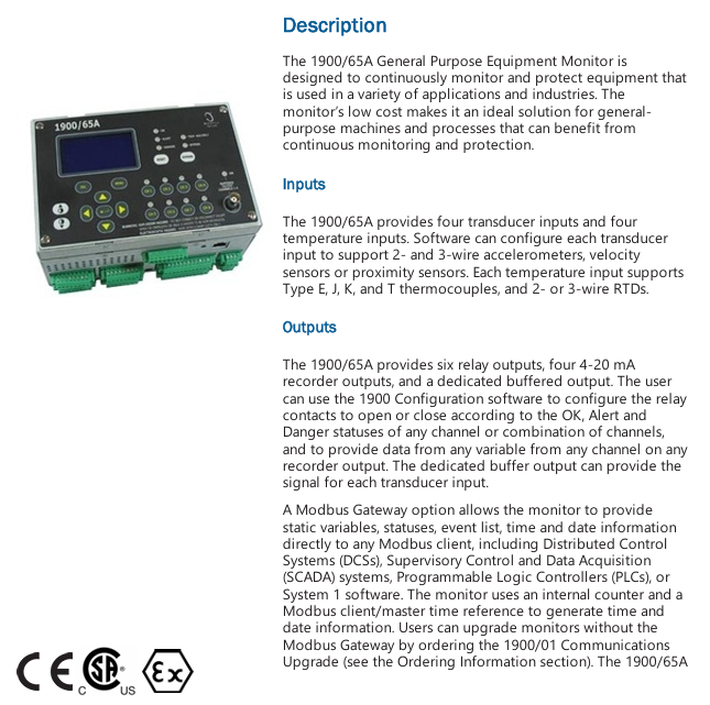
The 1900/65A General Purpose Equipment Monitor is designed to continuously monitor and protect equipment that is used in a variety of applications and industries. The monitor’s low cost makes it an ideal solution for general purpose machines and processes that can benefit from continuous monitoring and protection.
Inputs
The 1900/65A provides four transducer inputs and four temperature inputs. Software can configure each transducer input to support 2- and 3-wire accelerometers, velocity sensors or proximity sensors. Each temperature input supports Type E, J, K, and T thermocouples, and 2- or 3-wire RTDs.
Outputs
The 1900/65A provides six relay outputs, four 4-20 mA recorder outputs, and a dedicated buffered output. The user can use the 1900 Configuration software to configure the relay contacts to open or close according to the OK, Alert and
Danger statuses of any channel or combination of channels, and to provide data from any variable from any channel on any recorder output. The dedicated buffer output can provide the signal for each transducer input.
A Modbus Gateway option allows the monitor to provide static variables, statuses, event list, time and date information directly to any Modbus client, including Distributed Control Systems (DCSs), Supervisory Control and Data Acquisition (SCADA) systems, Programmable Logic Controllers (PLCs), or System 1 software. The monitor uses an internal counter and a Modbus client/master time reference to generate time and date information. Users can upgrade monitors without the Modbus Gateway by ordering the 1900/01 Communications Upgrade (see the Ordering Information section). The 1900/65A supports Modbus communications via Ethernet and a software-configurable RS232/485 serial port.
Configuration
The user defines monitor operation and the Modbus Gateway register map by using
software running on a laptop or PC to create a configuration file and download the file to the monitor through the built-in Ethernet connection. The 1900/65A permanently stores configuration information in non-volatile memory, and can upload this information to the PC for changes.
Display Module
The 1900/65A supports an optional display/keypad to view channel information or
make minor configuration changes. This allows the 1900/65A to operate as a stand-alone package. If desired, the user can mount the display up to 75 metres (250 feet) from the Monitor Module.
Specifications
Inputs
Transducer Inputs
Users can configure Channels 1 through 4 to accept input from acceleration, velocity or displacement transducers.
Transducer Channel Types
Channel Types define the functionality for processing that will be applied to an input signal and the kind of variables or measurement values that will be derived from this input. Channel Types also define the kind of sensor that must be used. Transducer Channel Types include:
Acceleration or Reciprocating Acceleration
Velocity or Reciprocating Velocity
Radial Vibration (shaft vibration)
Thrust (shaft axial displacement)
Position
Speed
Acceleration and Reciprocating Acceleration Channel Types
The Acceleration Channel Type and Reciprocating Acceleration Channel Type support two- and three-wire acceleration sensors. The Reciprocating Acceleration
channel type has timed OK channel defeat disabled.
Acceleration Variables and Reciprocating Acceleration Variables
Acceleration Variables and Reciprocating Acceleration Variables are filtered and
processed measurements from raw transducer signals. The Acceleration
Channel Type and Reciprocating Acceleration Channel Type continuously processes up to four variables per channel.
Vibration:Up to three bandpass filtered amplitude measurements.
Acceleration :Users can apply the acceleration enveloping algorithm to one Acceleration or Reciprocating Acceleration Variable.
Enveloping:Bias Voltage Users may assign the value of the transducer bias voltage to any of the variables.
Filters
Vibration Variable: 0.5 Hz – 25 kHz configurable 4-pole high pass, 4-pole low-pass
Enveloping High-Pass:25 Hz to 5 kHz, configurable 4-pole
Enveloping Low-Pass:125 Hz to 25 kHz, configurable 2-pole
Enveloped Variable High Pass: 0.1 Hz min., but greater than Enveloped Variable low-pass 2-pole
Enveloped Variable Low Pass:Greater than Enveloped Variable high-pass and less than Enveloping high-pass 4-pole
Bias Filter:0.01 Hz 1-pole low-pass
OK Filter:2.4 kHz 1-pole low-pass
Full Scale Range
Vibration:20 to 500 m/s2 (2 to 50 g) peak and RMS
Enveloped:20 to 500 m/s2 (2 to 50 g) peak and RMS
Integrated:10 to 100 mm/s (0.4 to 4 in/s) peak and RMS
Bias Voltage:-24 V
Accuracy
Vibration Variables: ±1% of full scale range
Input Impedance
3-wire Voltage Mode;10 kΩ
Velocity and Reciprocating Velocity Channel Type
The Velocity Channel Type and Reciprocating Velocity Channel Type support two-wire and three-wire piezo velocity sensors.
Velocity Variables and Reciprocating Velocity Variables
Velocity Variables and Reciprocating Velocity Variables are filtered and processed measurements from raw transducer signals. The Velocity Channel Type and Reciprocating Velocity Channel Type support up to four continuously calculated variables per channel.
Vibration
Up to three bandpass filtered amplitude measurements
Bias Voltage
Users may assign the value of the transducer bias voltage to any of the variables.
Configurable Options
Each variable is independently configured with the following options.
Vibration Variables:
Peak or RMS Metric or English units
Filter corner frequencies
Full-scale range
Velocity integrated to displacement
Filters
Vibration Variables:0.5 Hz to 5.5 kHz, configurable 8-pole high pass, 4-pole low-pass
Bias Filter:0.09 Hz 1-pole low-pass
OK Filter:2.4 kHz 1-pole low-pass
Full Scale Range
Vibration:10 to 50 mm/s (0.5 to 2 in/s) peak and RMS
Integrated:100 to 500 μm (5 to 20 mils) peak to peak
Bias Voltage:-24 V
Accuracy
Vibration Variables: ±1% of full scale range
Input Impedance
3-Wire Voltage Mode:10 kΩ
Compliance and Certifications
FCC
This device complies with part 15 of the FCC Rules.
Operation is subject to the following two conditions:
This device may not cause harmful interference.
This device must accept any interference received, including interference that may cause undesired operation.
EMC
EN 61000-6-2: 2005
EN 61000-6-4: 2007 +A1:2001
EMC Directive 2014/30/EU
Electrical Safety
EN 61010-1: 2010
LV Directive 2014/35/EU
ATEX
EN 60079-0: 2012
EN 60079-15: 2010
ATEX Directive 2014/34/EU
RoHS
RoHS Directive 2011/65/EU
Maritime
ABS 2009 Steel Vessels Rules
1-1-4/7.7,4-8-3/1.11.1,4-9-7/13
Hazardous Area Approvals
This monitor is not certified for installation in Class 1 Div 1 locations, but it will support transducers installed in Div 1 locations via the use of galvanic isolators and barriers. If galvanic isolators are used, no change is necessary to the installation. A removable ground jumper allows the monitor to support zener barrier installations. Removing the jumper will disconnect circuit common from chassis at the monitor so that chassis can be connected at the barrier.
Special Considerations
Hazardous area installations require relay contact voltages below 30 Vac rms, or 30 Vdc to minimize hazard.Hazardous area installations require relay contact amperages below 5 Amps DC, or AC to minimize hazard
Leave a comment
Your email address will not be published. Required fields are marked *